Scene Lights
Last Updated Time: 12/26/2023
Overview
The light of the light source has an effect on objects, and lighting in the Engine is used to simulate how light travels and interacts in the real world. The Engine uses detailed models to analyze the mechanics of how lights work to achieve more realistic effects, or uses simplified models to achieve more stylized effects.
Creating Scene Lights
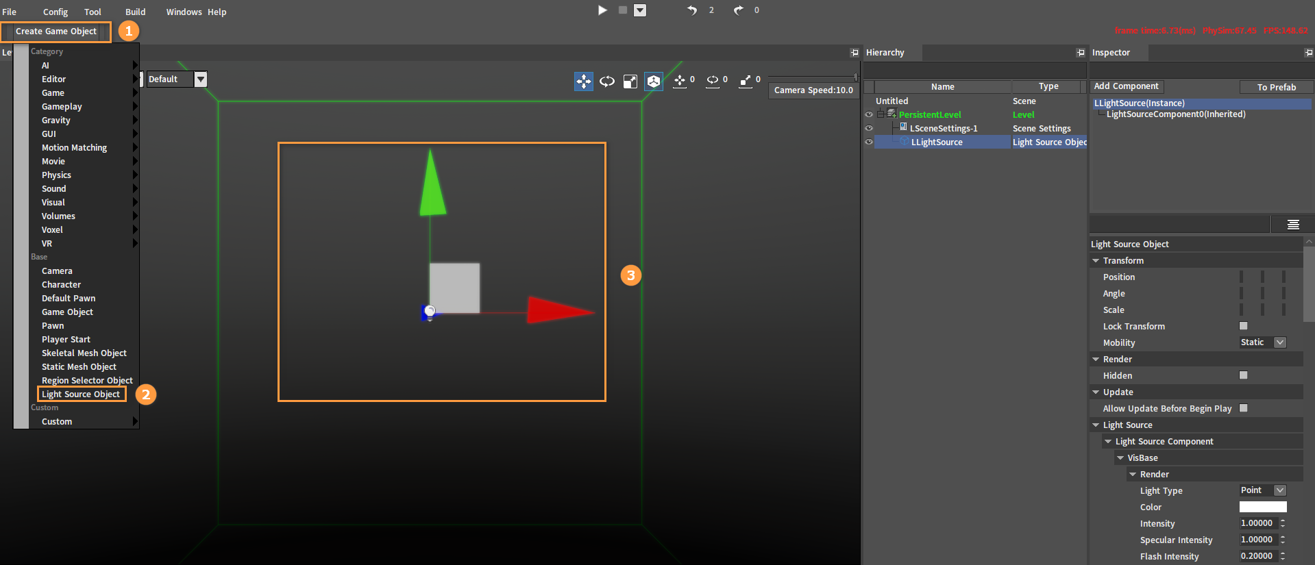
In the Component Editor, click Create Game Object -> Light Source Object to create a Light Source Object.
Scene Light Settings
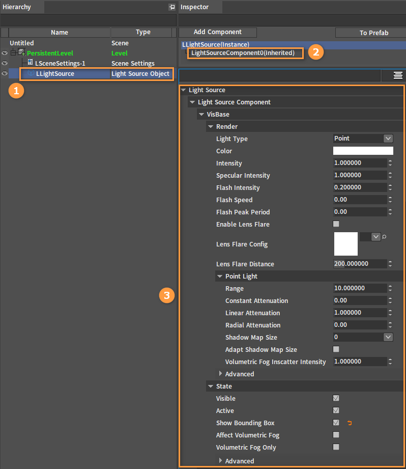
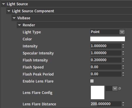
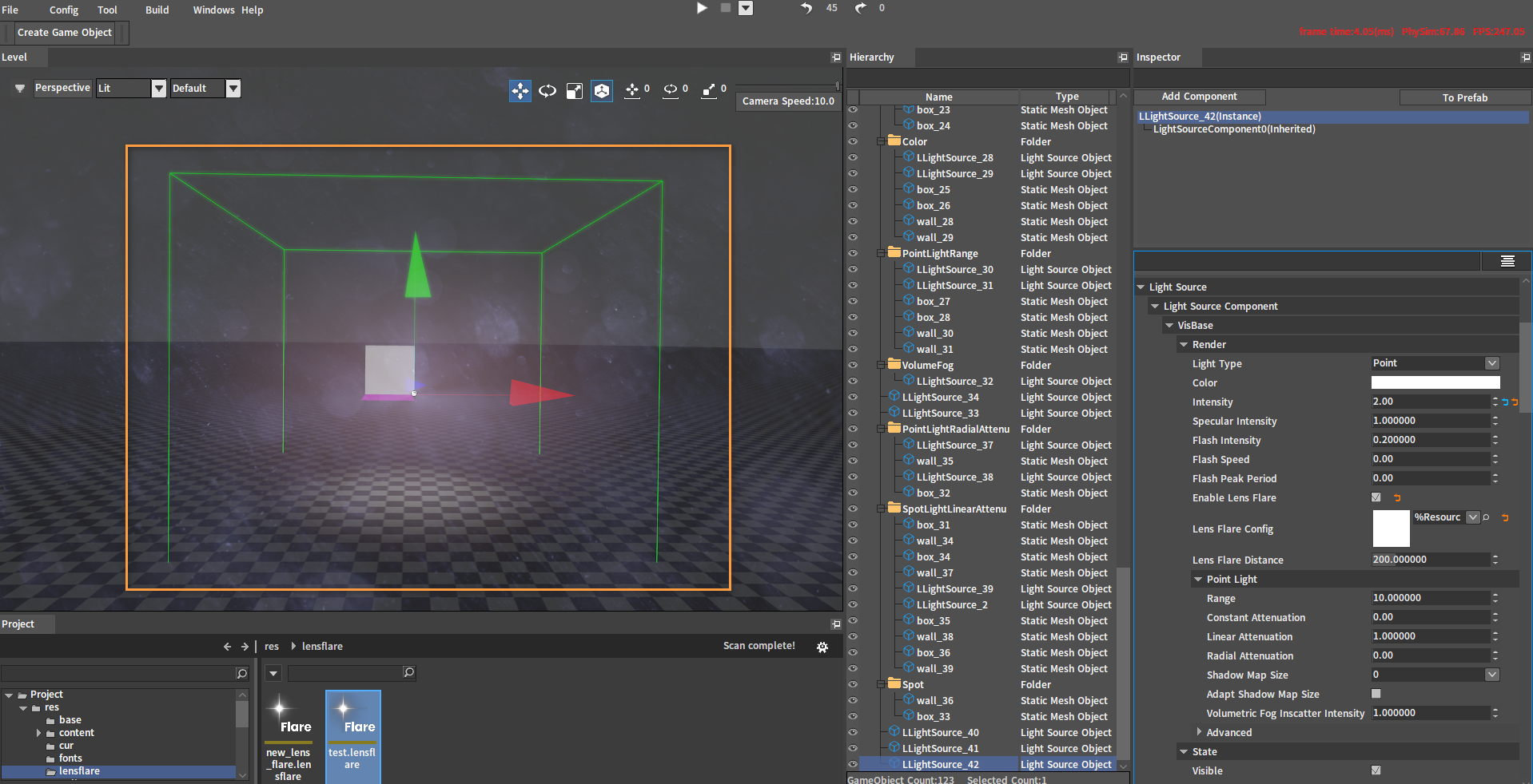
Select the created Light Source Object (LLightSource) in the Hierarchy panel, then select LightSourceComponent0(Inherited) in the Inspector panel, and the light related settings can be made in the VisBase category below.
Scene Light Types
The Engine provides different types of lights, which can be selected according to the needs of different scenes.
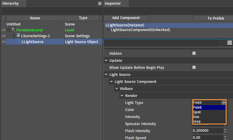
The Point light, Spot light, Box light and Area light can be selected in the Light Type property of the Light Source Object.
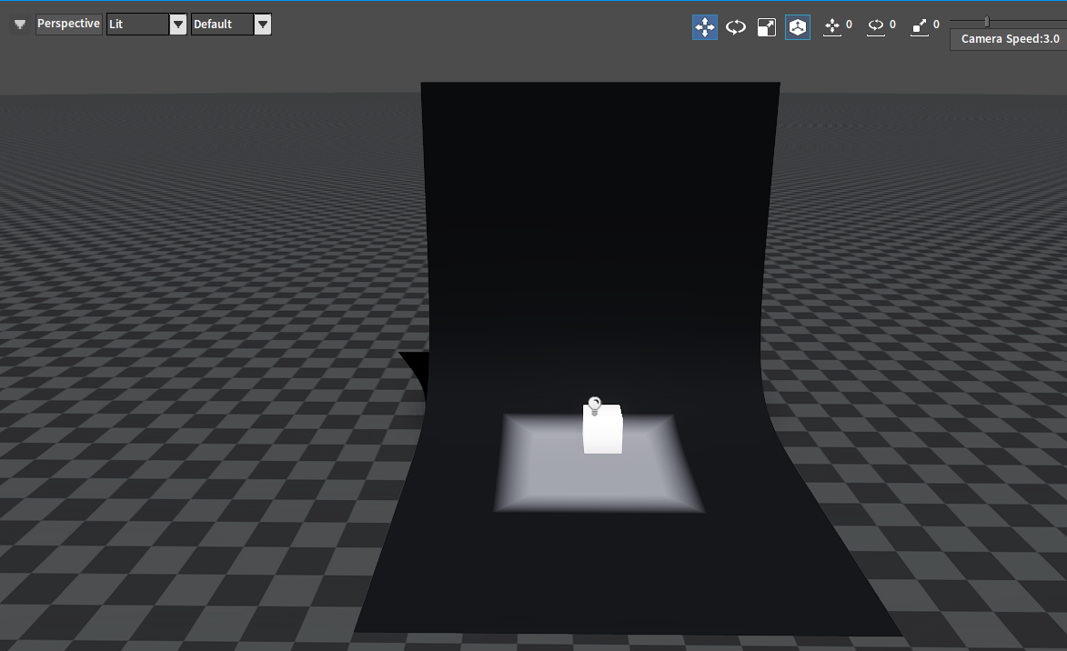
Point
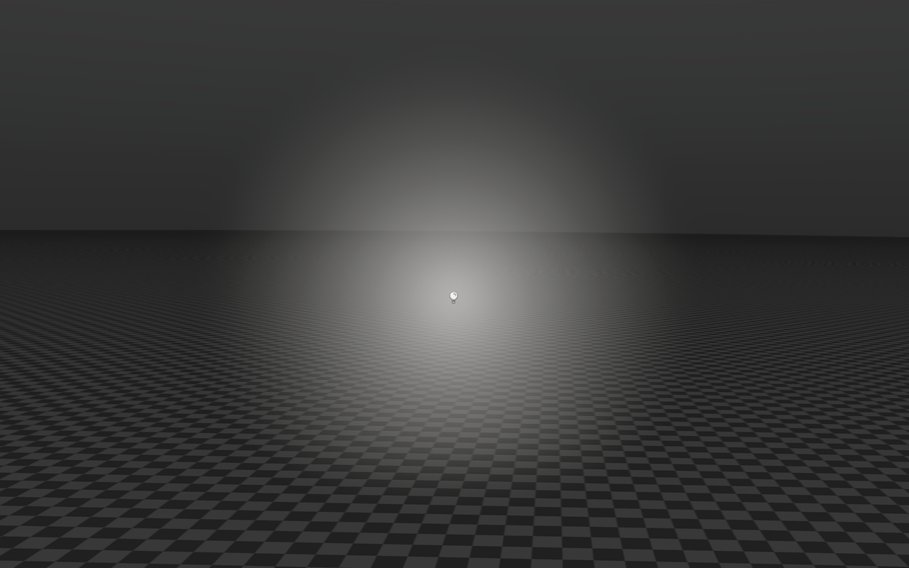
The Point light can be seen as a point, from which light radiates out in space and emits evenly in all directions. The Point light is usually used to simulate the light of a bulb.
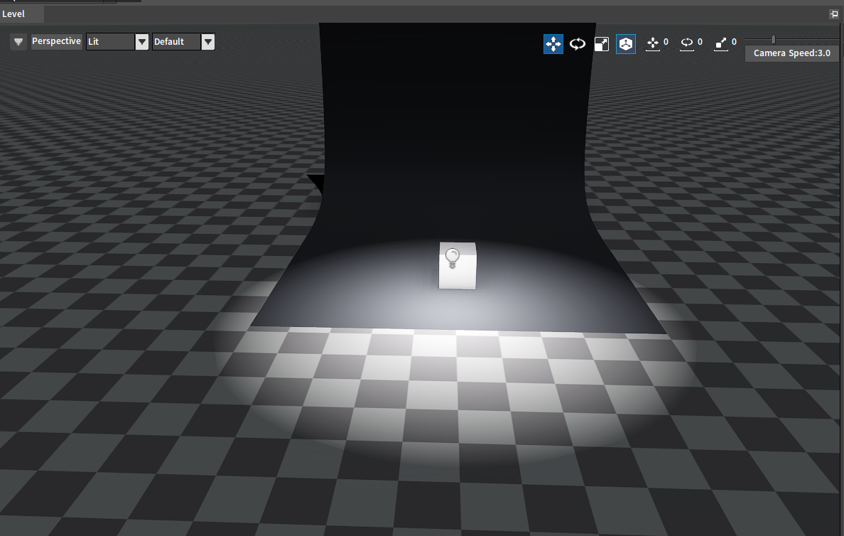
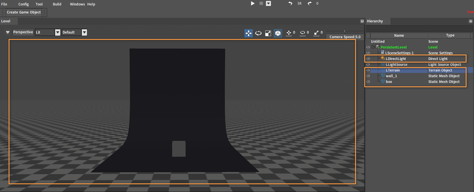
You can add Terrain Objects, Direct Lights, and model objects to the scene first in order to see the effect of the scene light.
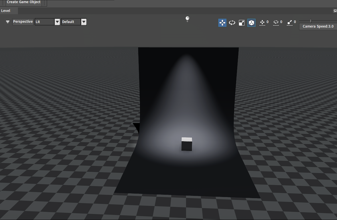
Spot
The Spot light is a directional light that emits light from a single point of a cone to simulate the effect of a focused beam of light. The Spot light is generally used to simulate lights of flashlights, stage lights, etc.
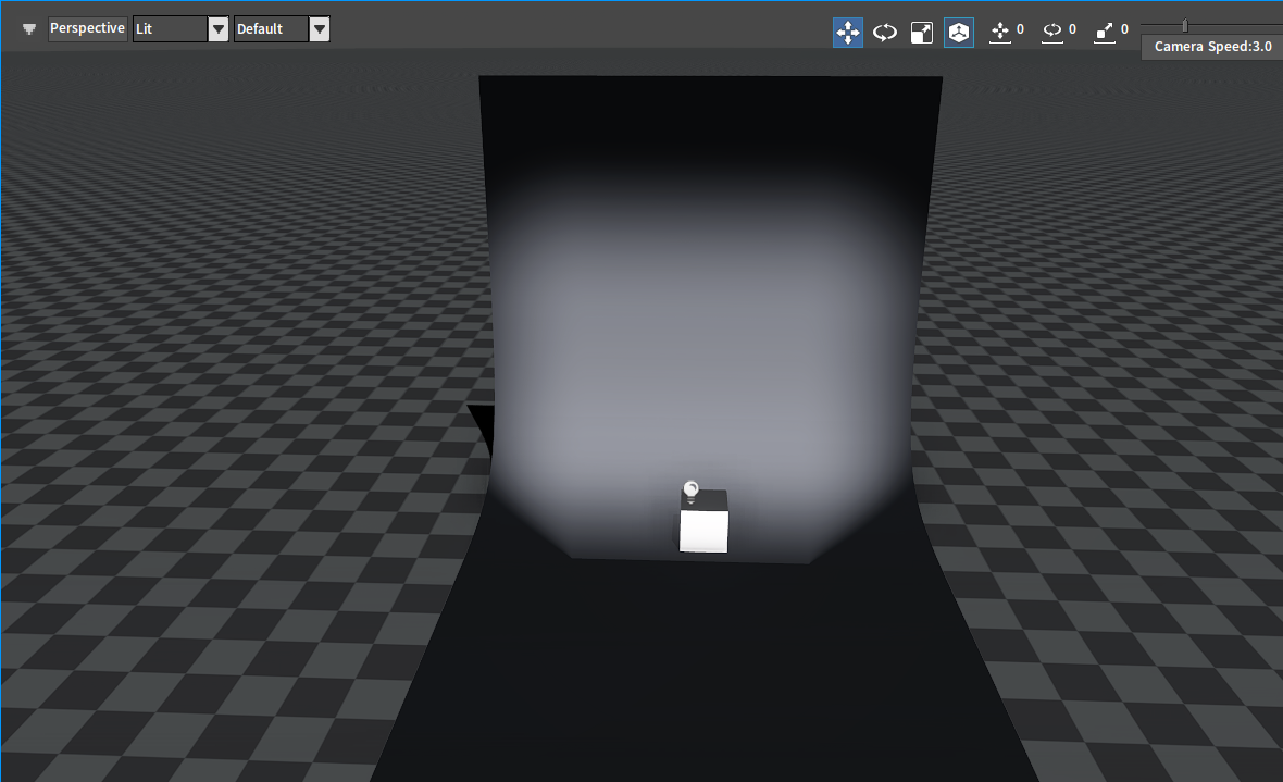
Box
The Box light can be seen as a box that emits light from inside. The Box light is generally used to simulate lights of indoor scenes such as lamps, windows, etc.
Area
The Area light can be seen as a light with a planar shape and a surface that emits light. The Area light is generally used to simulate large-area lights, such as floors, walls, etc.
Scene Light Properties
Basic Properties of Lights
The following are the basic properties of scene lights.
| Property | Description |
|---|---|
| Color | The color that the light emits. |
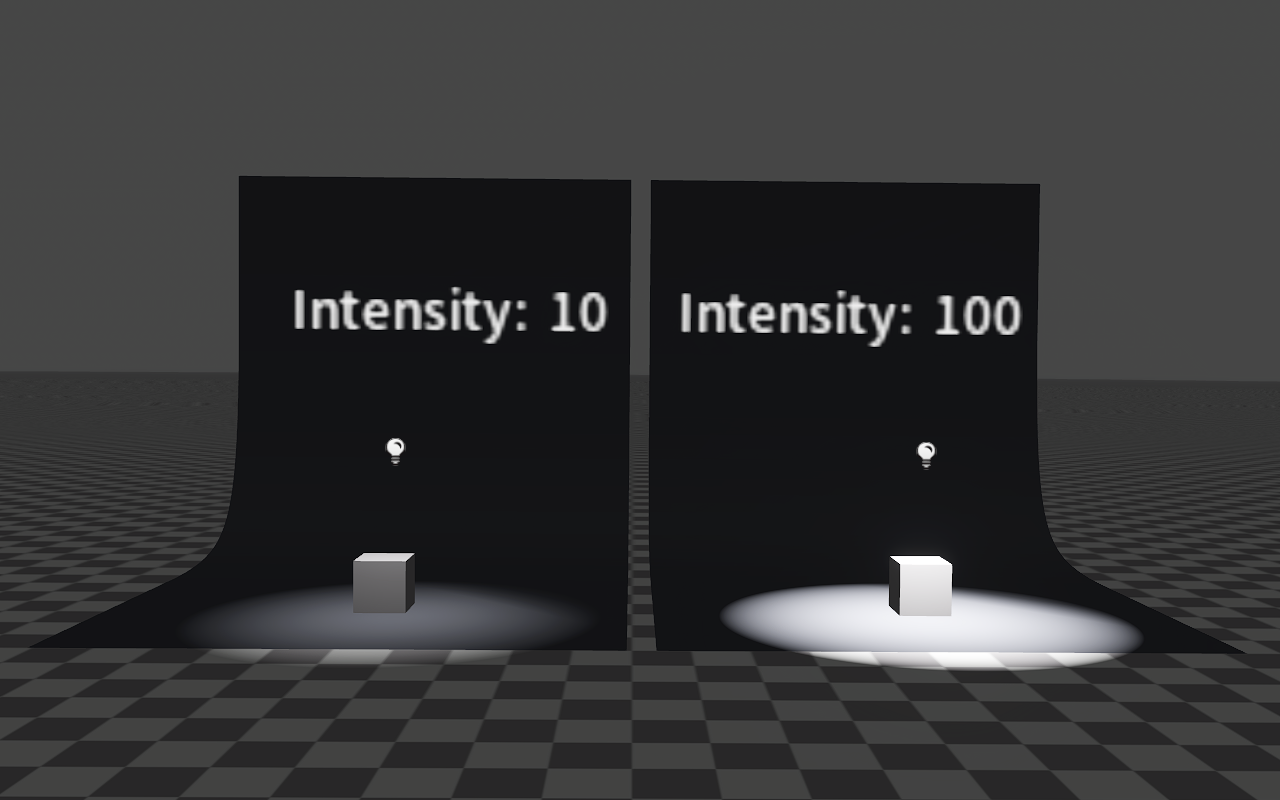
| Intensity | The total energy that the light emits. |
| Specular Intensity | Adjust the intensity of the specular light. |
| Flash Intensity | Flashing brightness offset factor (multiply with Intensity). |
| Flash Speed | Fade in and fade out time when flashing. |
| Flash Peak Period | The sum of the time to keep the brightest state and the time to keep the darkest state when flashing. |
| Enable Lens Flare | Enable the lens effect. When enabled, it will simulate the glass blur effect when the lens is looking towards the light. |
| Lens Flare Config | Lens effect Configuration file. |
| Lens Flare Distance | Lens effect attenuation distance. |
Effects of Basic Properties
Color
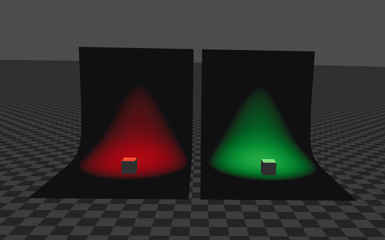
Intensity
Specular Intensity
The image below shows the specular effects reflected after the Point light illuminates the mirror.
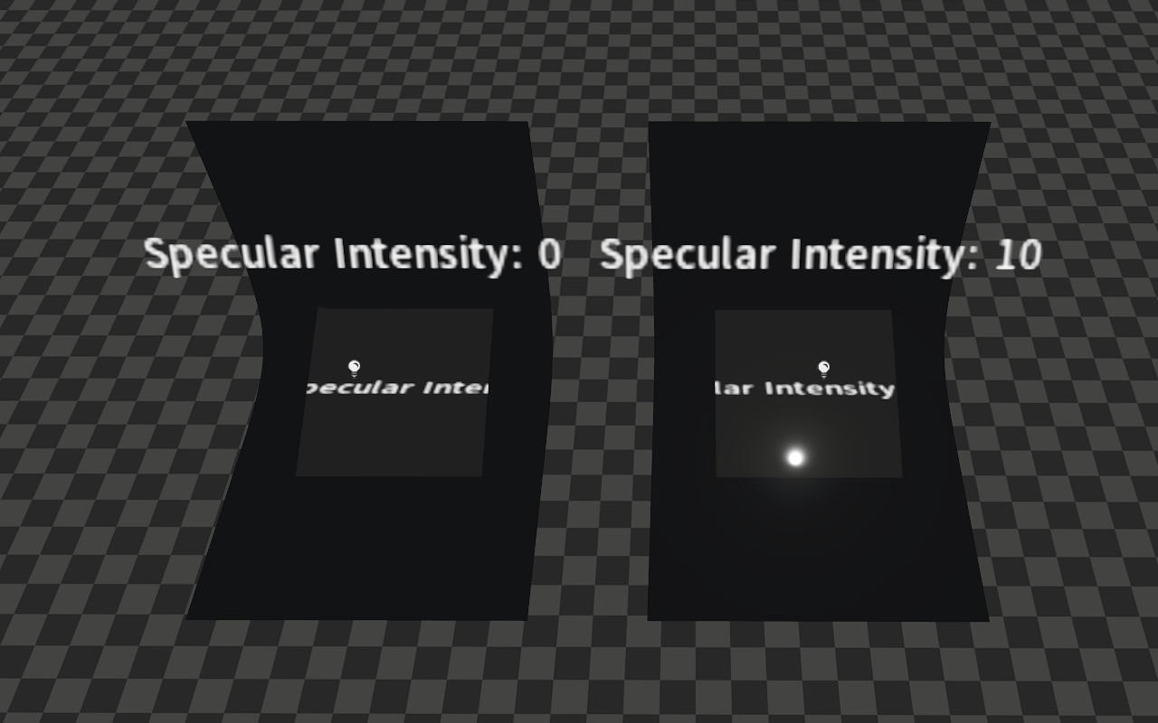
Place a mirror in the scene and use it to view the specular effects reflected after the scene light illuminates the mirror.
Flashing
Different flashing effects can be achieved by modifying the light's properties Flash Intensity, Flash Speed and Flash Peak Period.
The image below shows the effect when Flash Intensity=1, Flash Speed=2, and Flash Peak Period=0.5.
Lens Flare
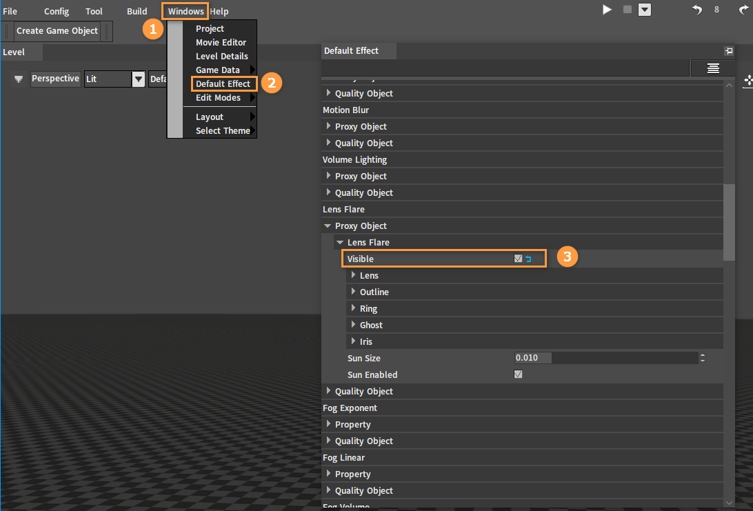
To enable the Lens Flare effect of the scene light, you need to enable the global Lens Flare effect first. Click Windows -> Default Effect in the Editor, then in the Default Effect window, check Lens Flare -> Proxy Object -> Lens Flare -> Visible.
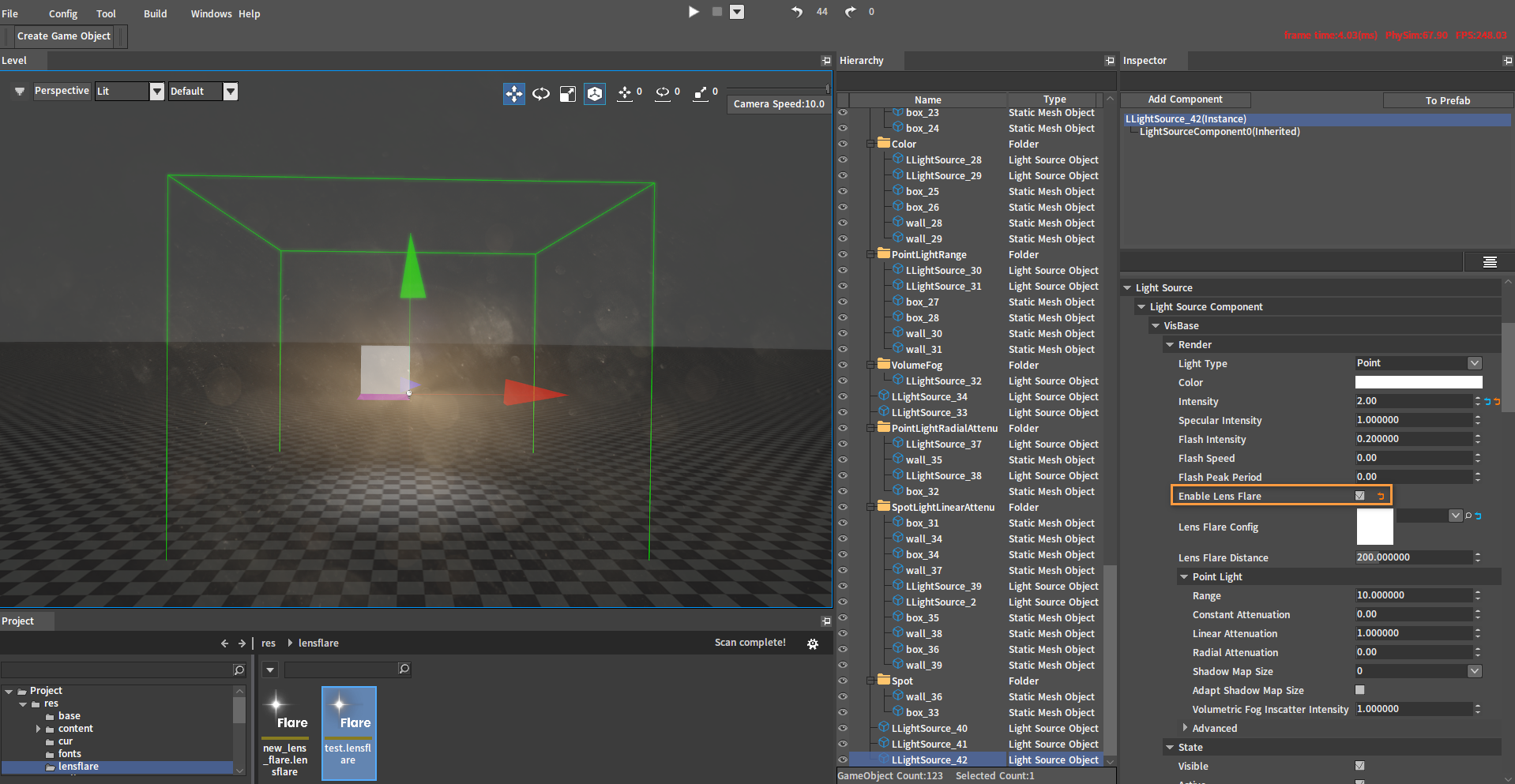
Enable Lens Flare
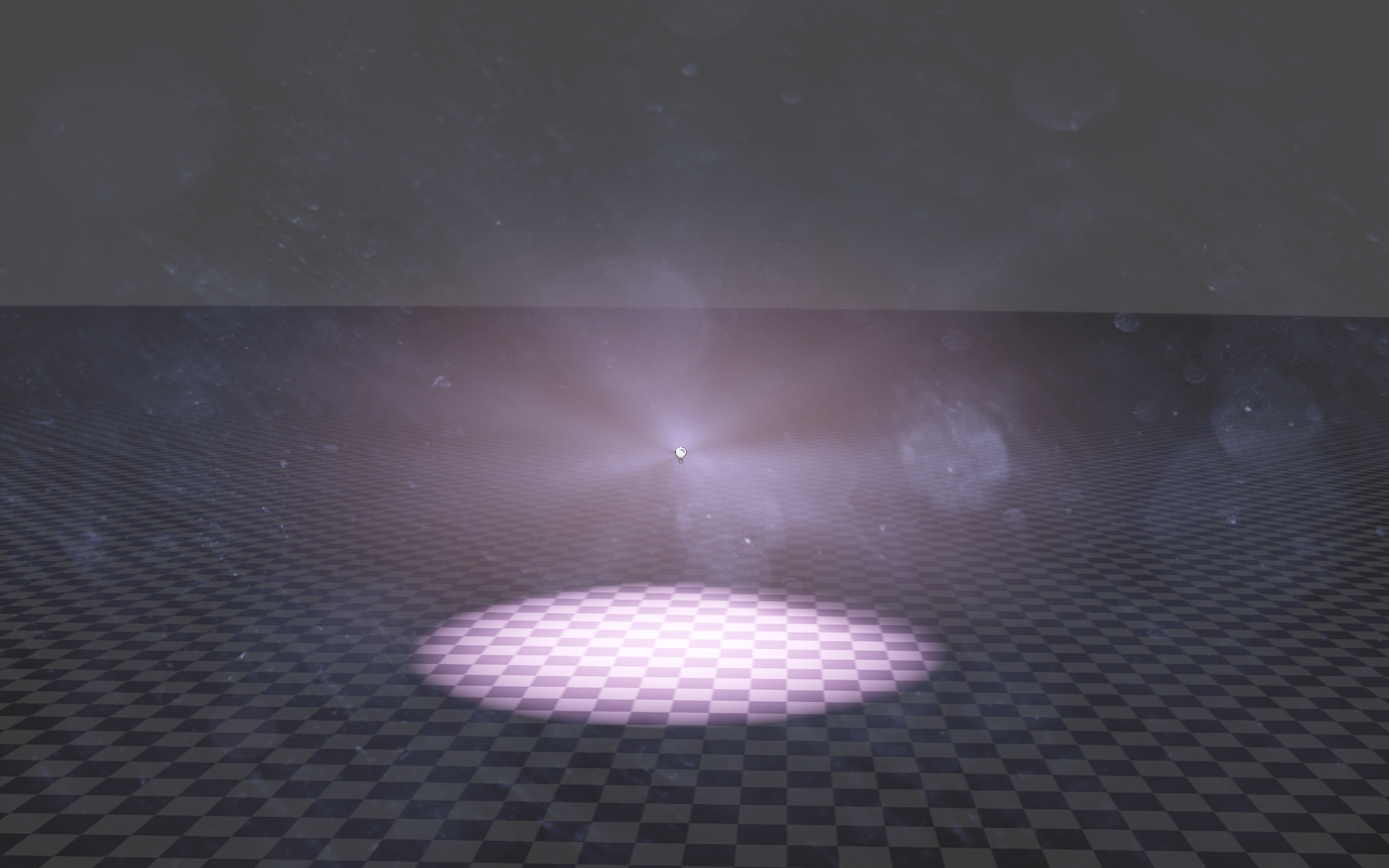
Check the Enable Lens Flare property of the light to see its Lens Flare effect.
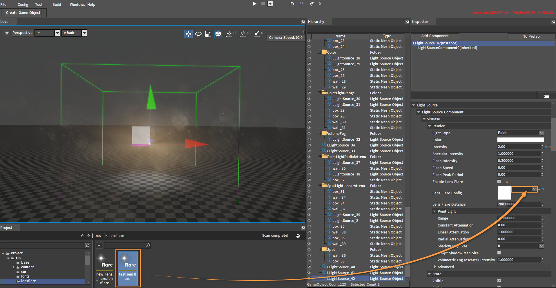
Lens Flare Config
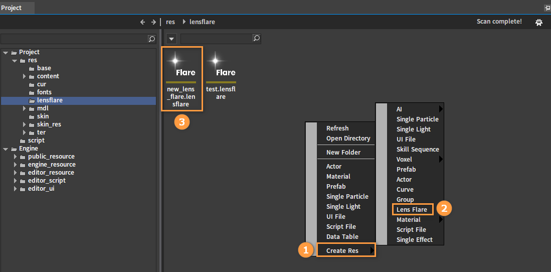
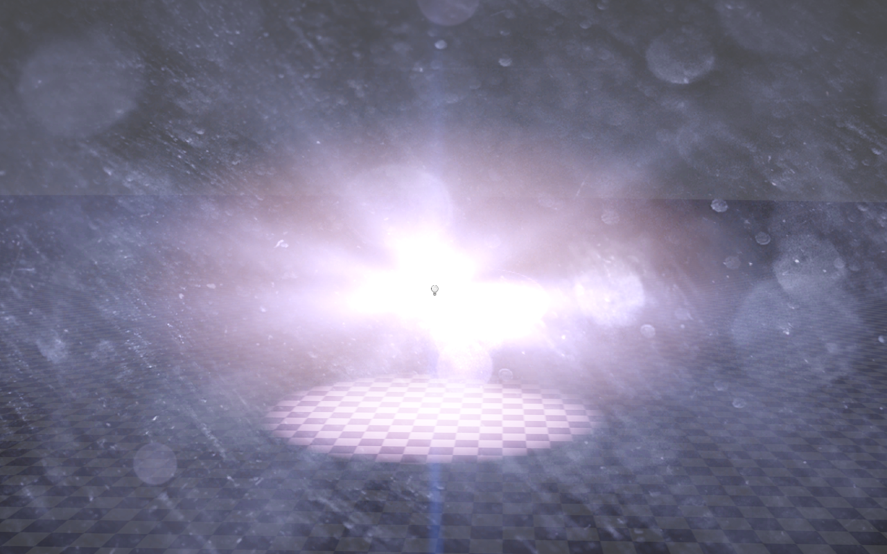
Drag a Lens Flare file (*.lensflare) from the Project panel into Lens Flare Config and the configuration of the file will override that of the global Lens Flare.
After configuration:
Right-click on the blank space of the Resource Preview window, then click Create Resource -> Lens Flare to create a Lens Flare file. Double-click the file to edit it.
Lens Flare Distance
Effects of different Lens Flare Distances with the same distance from the light.
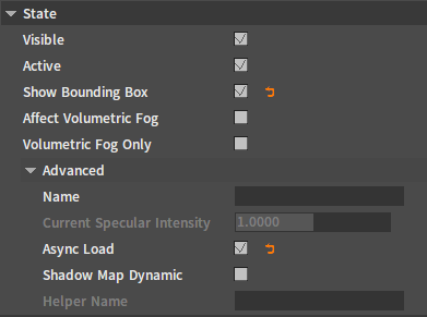
State Properties
The following are the properties under the State category of scene lights.
| Property | Description |
|---|---|
| Visible | Whether the light is displayed in the scene. |
| Active | Enable the light effect. |
| Show Bounding Box | Whether to display the wireframe of the light range. |
| Affect Volumetric Fog | Enable the effect of the light illuminating in the fog. |
| Volumetric Fog Only | Show only the effect of the light illuminating in the fog, not the effect of the light illuminating on the ground/objects. |
| Name | The light name. |
| Current Specular Intensity | Unmodifiable |
| Async Load | Speed up map loading. |
| Shadow Map Dynamic | Auto refresh shadow map size. |
| Helper Name | Unmodifiable |
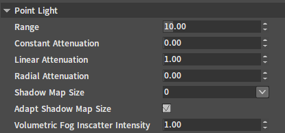
Point Light Properties
The following are properties related to the Point Light settings.
| Property | Description |
|---|---|
| Range | Limit the light's visible range. |
| Constant Attenuation | Constant attenuation factor. |
| Linear Attenuation | Linear attenuation factor. |
| Radial Attenuation | Radial attenuation factor. |
| Shadow Map Size | The size of the shadow map displayed when creating a shadow. |
| Adapt Shadow Map Size | When enabled, the shadow map size can be automatically adjusted according to the view distance. |
| Volumetric Fog Inscatter Intensity | Can be used to control the intensity of the volumetric fog after using it. |
Property Effects
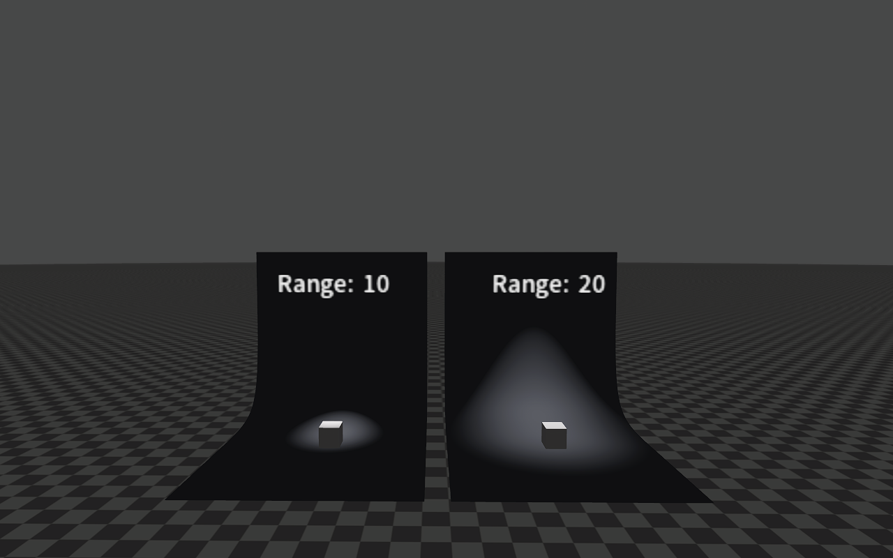
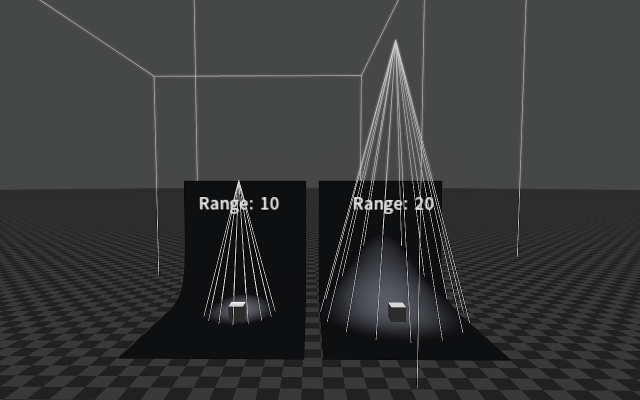
Range
The image below shows Point Lights with different Ranges. When a light is selected, you can see the area surrounded by a wireframe, which represents the light's visible range.
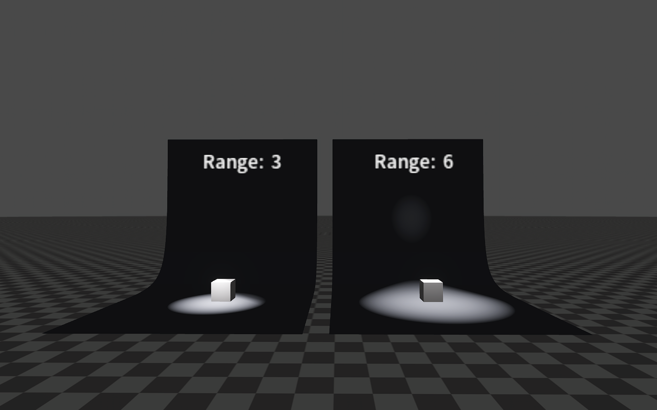
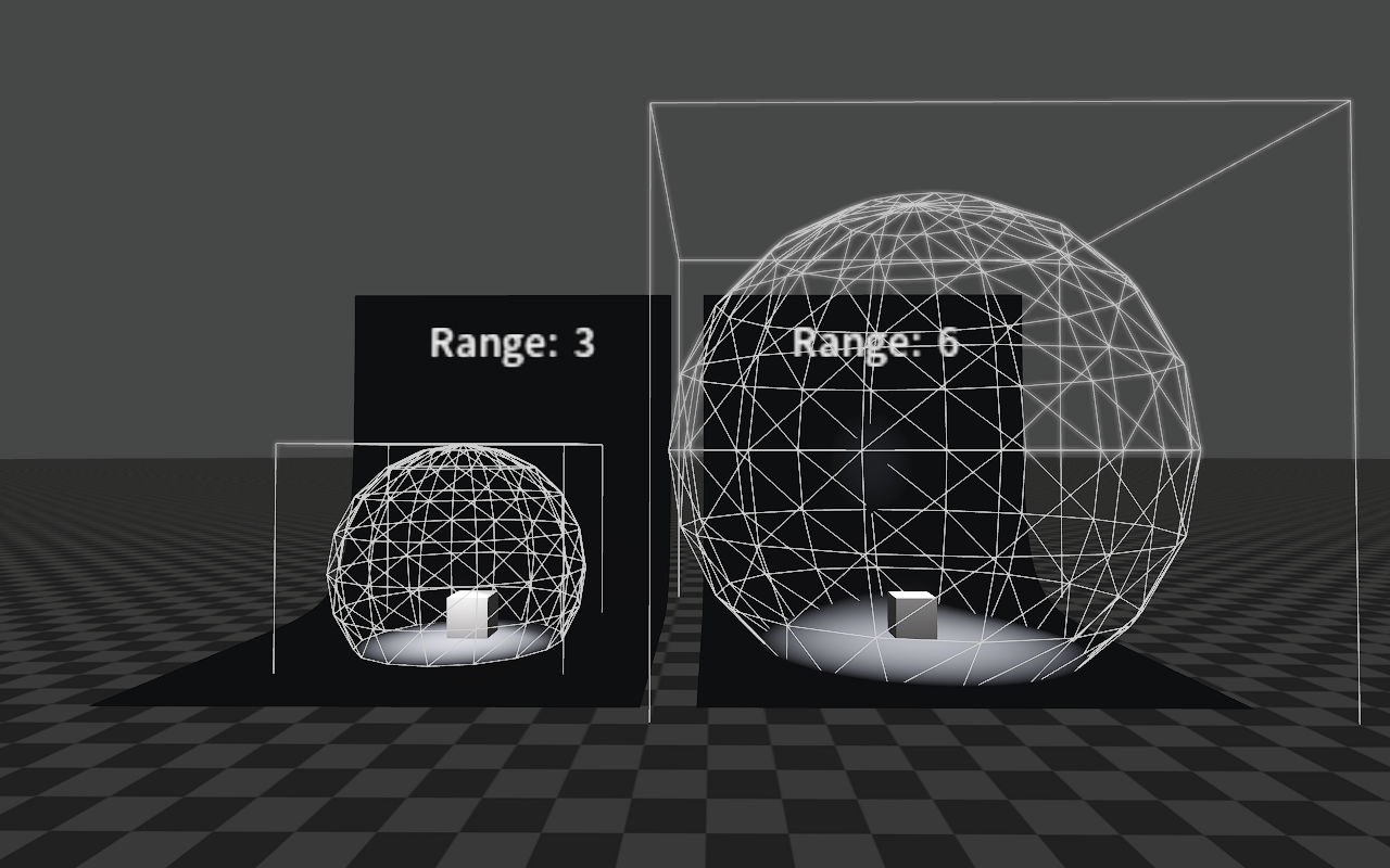
Wireframes can be turned on/off via the Show Bounding Box property of the light.
Attenuation
Properties Constant Attenuation, Linear Attenuation and Radial Attenuation are used to adjust the light intensity of the light area.
The attenuation equation is:
d = max(d + Attenuation Coefficient 0, 0.0F);
float inten = max(0.0F, 1.0F - (Attenuation Coefficient 1 * d + Attenuation Coefficient 2 * d * d));
//If the values of Attenuation Coefficient 0 and Attenuation Coefficient 2 are both 0, the following equation will be used.
float inten = max(0.0F, 1.0F - Attenuation Coefficient 1 * d);

//d is the distance from the point in the light area to the light center.
//The result of the above equation is the light intensity.
Among them, Attenuation Coefficient 0 is Constant Attenuation, Attenuation Coefficient 1 is Linear Attenuation, and Attenuation Coefficient 2 is Radial Attenuation.
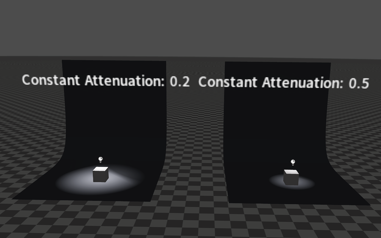
Constant Attenuation
The image below shows the effects of different Constant Attenuation when both Linear Attenuation are 1 and both Radial Attenuation are 0.
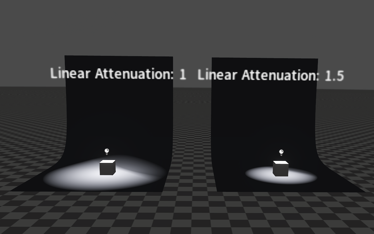
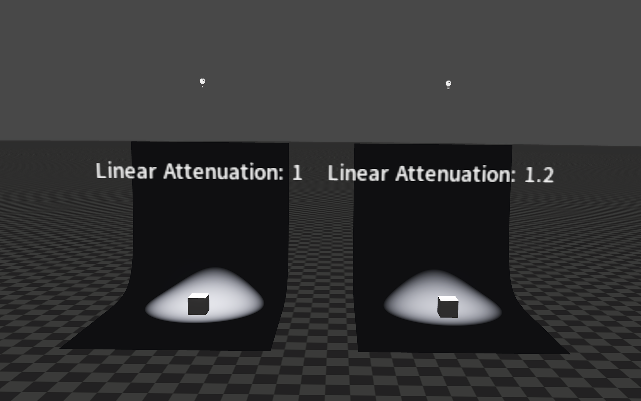
Linear Attenuation
The image below shows the effects of different Linear Attenuation when both Constant Attenuation are 0 and both Radial Attenuation are 0.
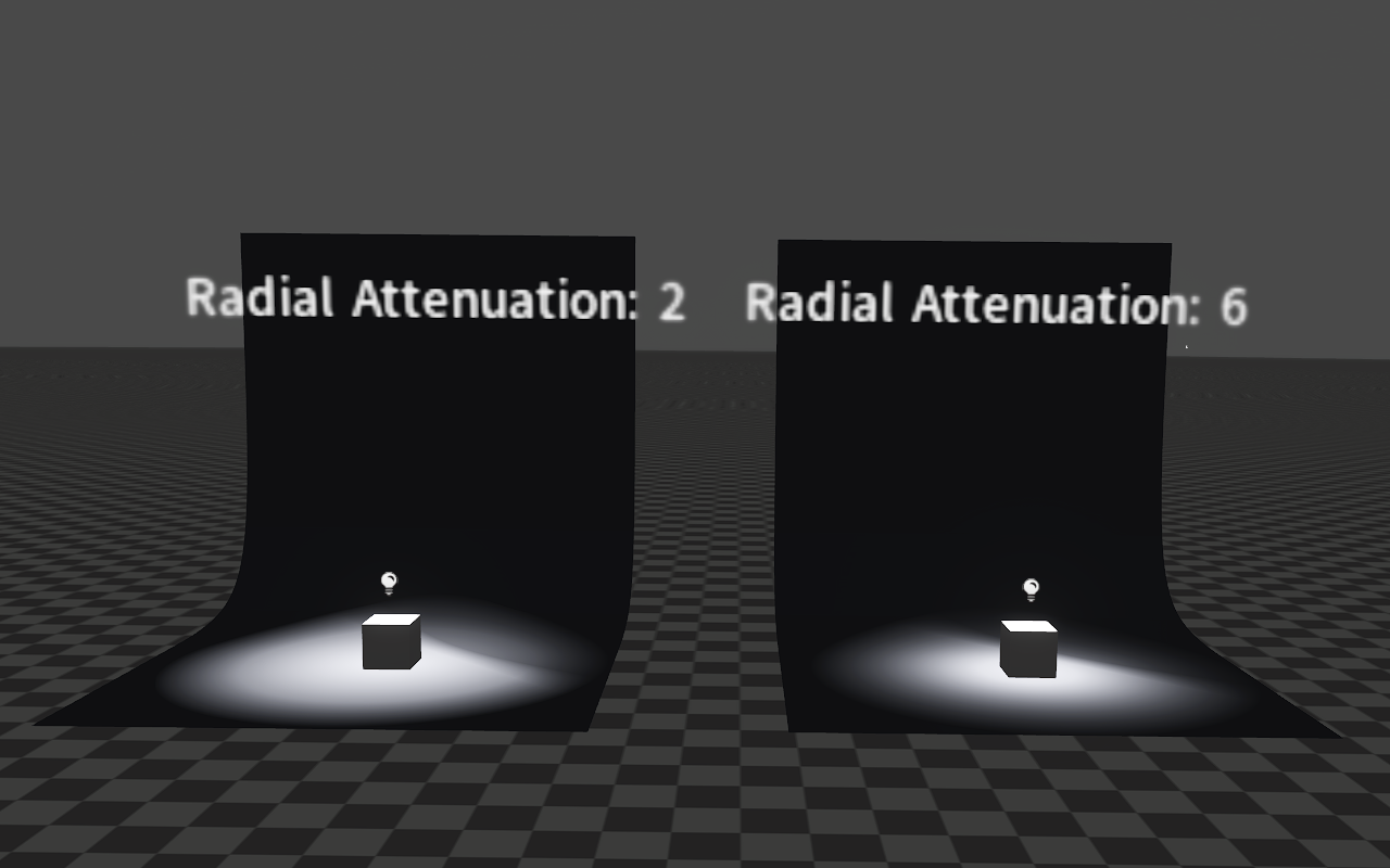
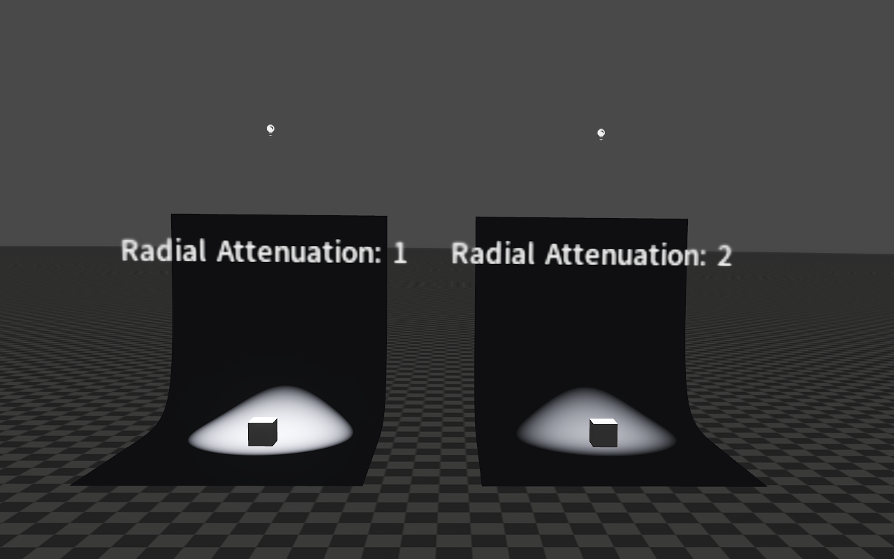
Radial Attenuation
The image below shows the effects of different Radial Attenuation when both Constant Attenuation are 0 and both Linear Attenuation are 1.
Volumetric Fog Inscatter Intensity
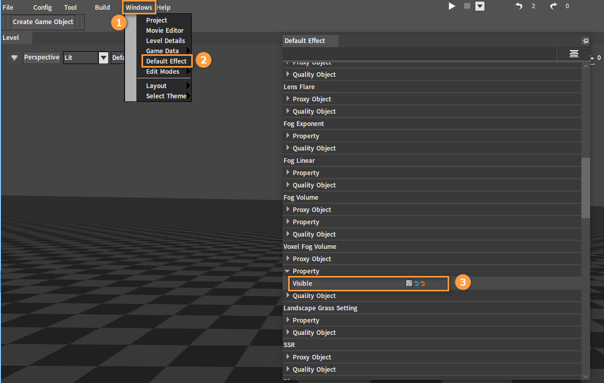
First you need to enable the Voxel Fog Volume effect. In the Editor, click Windows -> Default Effect, then in the Default Effect window, check Voxel Fog Volume -> Property -> Visible.
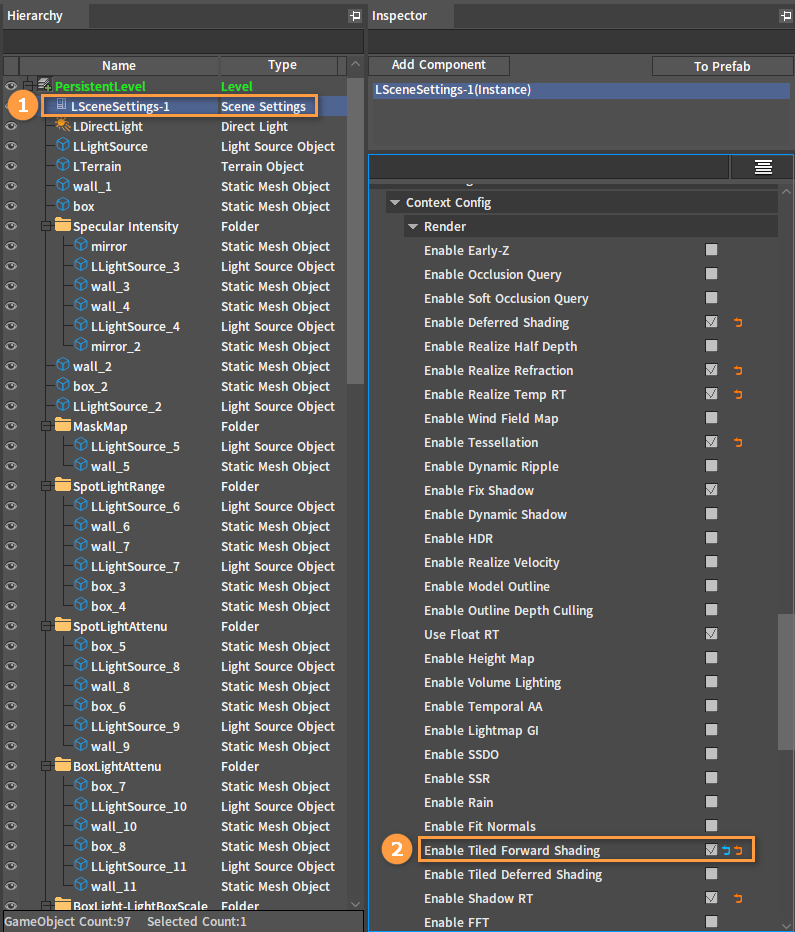
Select LSceneSettings-1 in the Hierarchy panel and check the Enable Tiled Forward Shading property under Context Config in the Inspector panel.
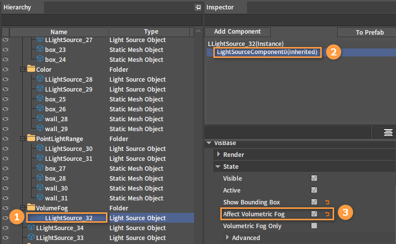
Select the Light Source Object in the Hierarchy panel, select LightSourceComponent0(Inherited) in the Inspector panel, and then check VisBase -> State -> Affect Volumetric Fog.
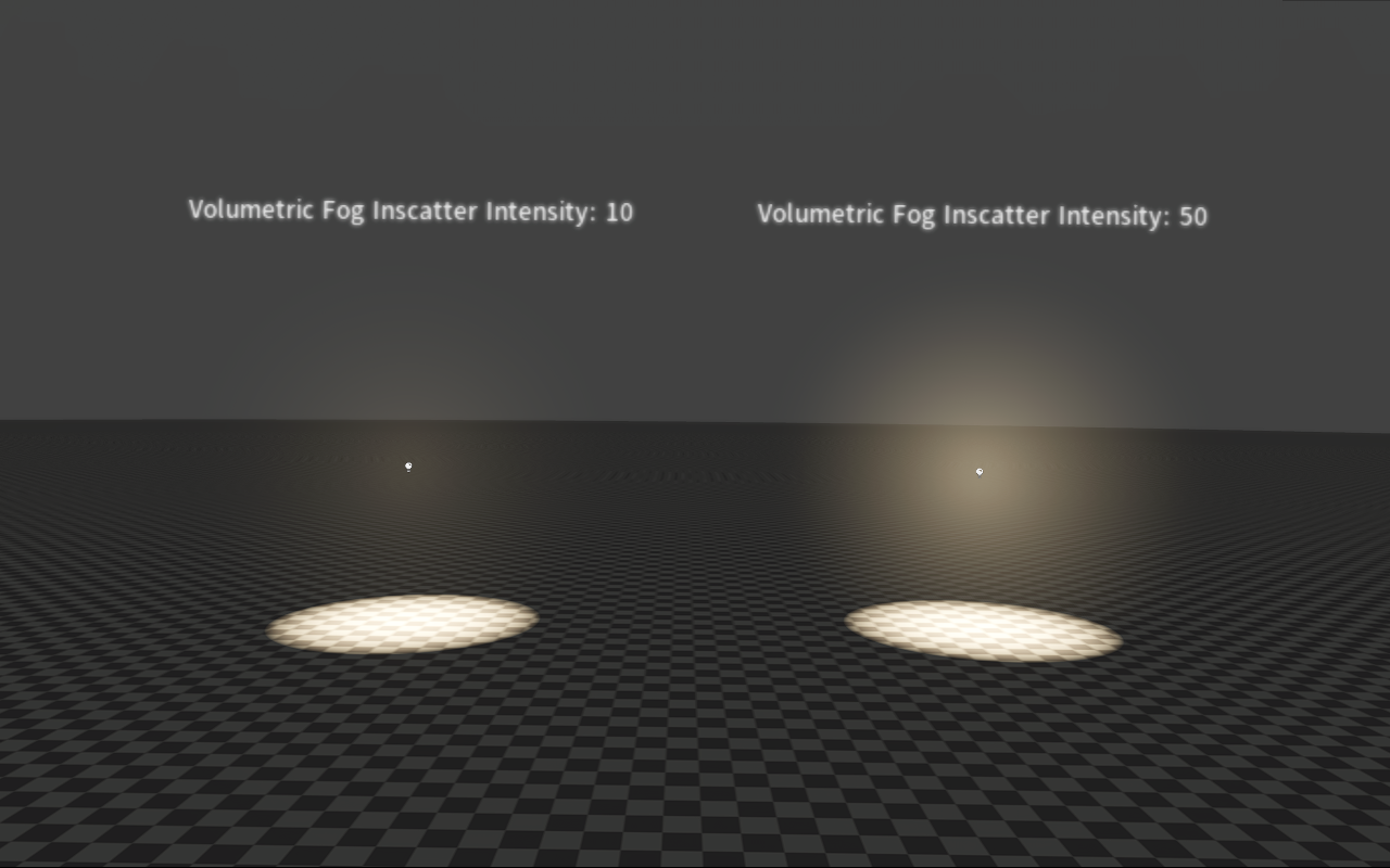
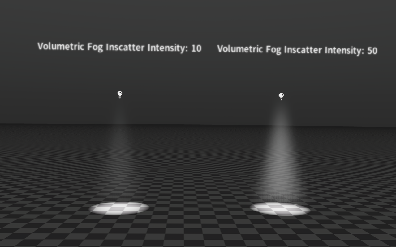
The volumetric fog intensity can be controlled by adjusting the Volumetric Fog Inscatter Intensity property of the light.
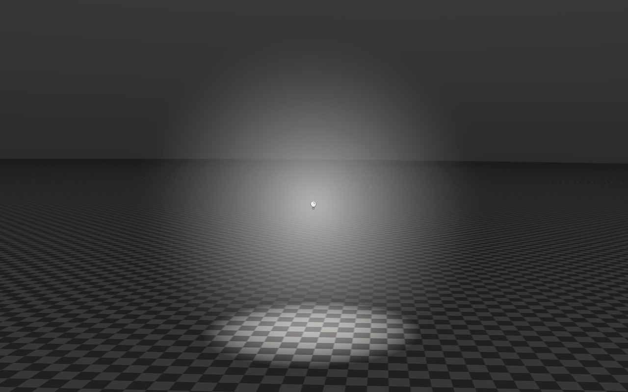
On the basis of the above, the effects of turning on and off State -> Volumetric Fog Only property of the light are shown below:
Spot Light Properties
The following are properties related to the Spot Light settings.
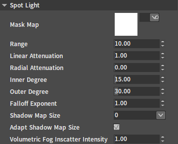
| Property | Description |
|---|---|
| Mask Map | Set the Mask Map that the Spot Light loads. |
| Range | Limit the light's visible range. |
| Linear Attenuation | Linear attenuation factor. |
| Radial Attenuation | Radial attenuation factor. |
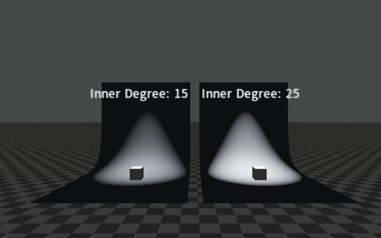
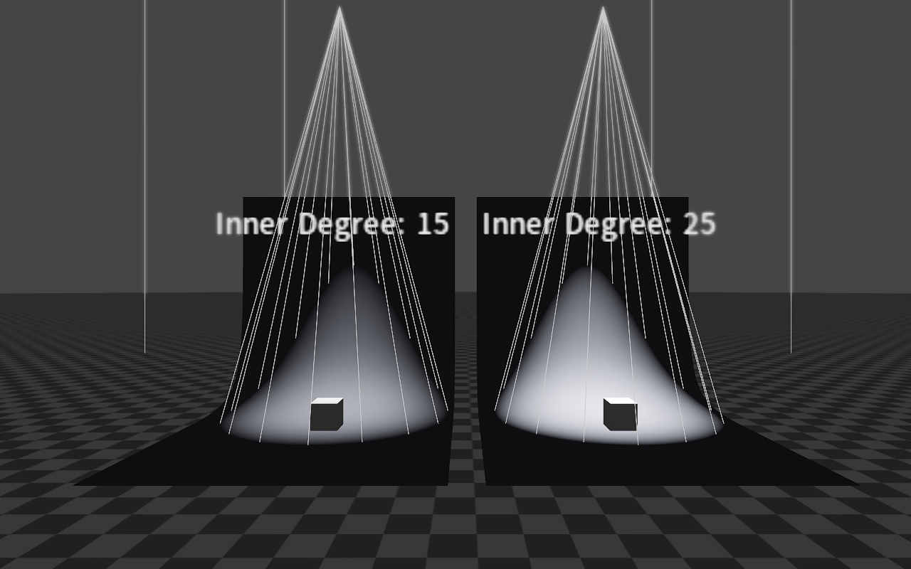
| Inner Degree | Set the inner cone angle of the Spot Light (in degrees). |
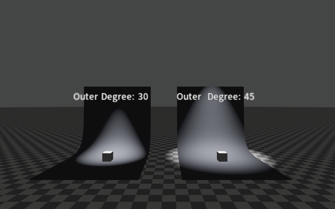
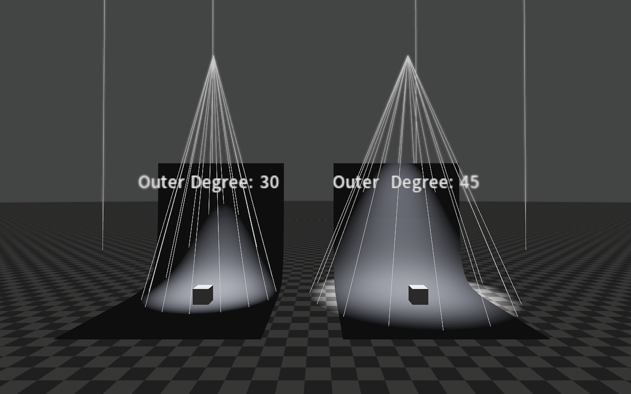
| Outer Degree | Set the outer cone angle of the Spot Light (in degrees). |
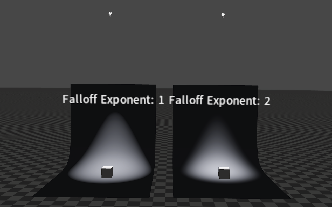
| Falloff Exponent | Exponential power of the Spot Light's intensity. |
| Shadow Map Size | The size of the shadow map displayed when creating a shadow. |
| Adapt Shadow Map Size | When enabled, the shadow map size can be automatically adjusted according to the view distance. |
| Volumetric Fog Inscatter Intensity | Can be used to control the intensity of the volumetric fog after using it. |
Property Effects
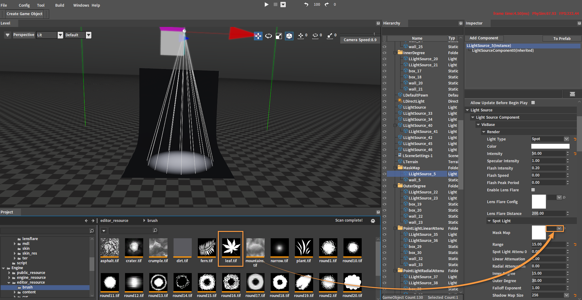
Mask Map
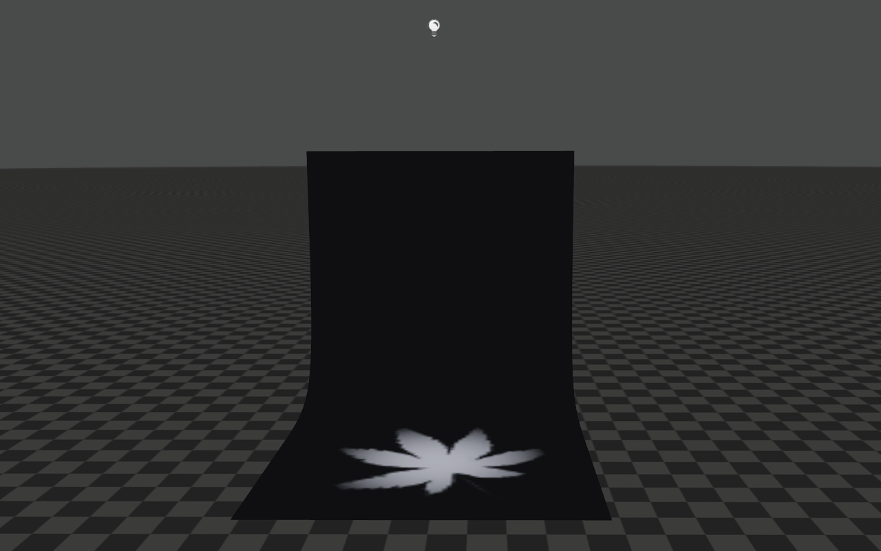
The Mask Map property is used to modify the Pattern of the area illuminated by the Spot Light.
Drag a Mask Map from the Resource Preview window to the Mask Map of the Light Source Object (LLightSource) to add a Mask Map to the light.
The effect:
Range
The Range property is used to adjust the area illuminated by the light. When a light is selected, you can see an area surrounded by a wireframe, which represents the light's visible range.
Attenuation
Properties Linear Attenuation and Radial Attenuation are used to adjust the light intensity of the light area.
The attenuation equation is:
float attenu = max(0.0F, 1.0F - (Attenuation Coefficient 1 * d + Attenuation Coefficient 2 * d * d));
//If the value of Attenuation Coefficient 2 is 0, the following equation will be used.
float attenu = max(0.0F, 1.0F - Attenuation Coefficient 1 * d);
//d is the distance from the point in the light area to the light center.
//The result of the above equation is the light intensity.
Among them, Attenuation Coefficient 1 is Linear Attenuation, and Attenuation Coefficient 2 is Radial Attenuation.
Linear Attenuation
The image below shows the effects of different Linear Attenuation when both Radial Attenuation are 0.
Radial Attenuation
The image below shows the effects of different Radial Attenuation when both Linear Attenuation are 0.
Inner Degree
The effects of different Inner Degrees when Outer Degree = 30.
Outer Degree
The effects of different Outer Degrees when Inner Degree = 15.
Falloff Exponent
Volumetric Fog Inscatter Intensity
For details on enabling and using the Volumetric Fog Inscatter Intensity effect of the Spot Light, please refer to the Volumetric Fog Inscatter Intensity of the Point Light.
Box Light Properties
The following are properties related to the Box Light settings.

| Property | Description |
|---|---|
| Constant Attenuation | Constant attenuation factor. |
| Linear Attenuation | Linear attenuation factor. |
| Radial Attenuation | Radial attenuation factor. |
| Light Box Scale | Box scale. |
Property Effects
Attenuation
Properties Constant Attenuation, Linear Attenuation and Radial Attenuation are used to adjust the light intensity of the light area.
The attenuation equation is:
d = max(d + Attenuation Coefficient 0, 0.0F);
float attenu = max(0.0F, 1.0F - (Attenuation Coefficient 1 * d + Attenuation Coefficient 2 * d * d));
//If the values of Attenuation Coefficient 0 and Attenuation Coefficient 2 are both 0, the following equation will be used.
float attenu = max(0.0F, 1.0F - c_Attenu.y * d);
//d is the distance from the point in the light area to the light center.
//The result of the above equation, attenu, will be multiplied by the light intensity.
Among them, Attenuation Coefficient 0 is Constant Attenuation, Attenuation Coefficient 1 is Linear Attenuation, and Attenuation Coefficient 2 is Radial Attenuation.
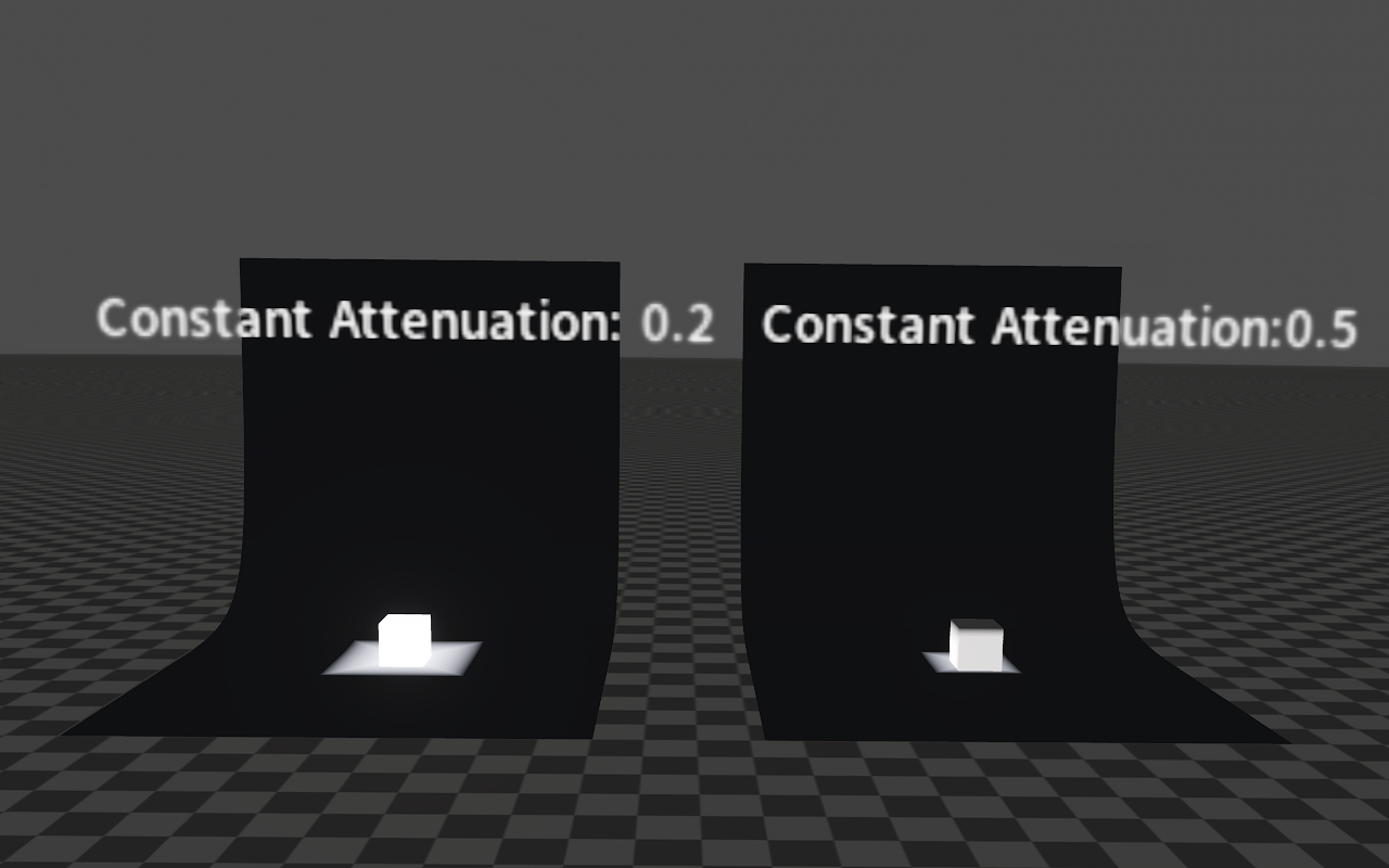
Constant Attenuation
The image below shows the effects of different Constant Attenuation when both Linear Attenuation are 1 and both Radial Attenuation are 0.
Linear Attenuation
The image below shows the effects of different Linear Attenuation when both Constant Attenuation are 0 and both Radial Attenuation are 0.

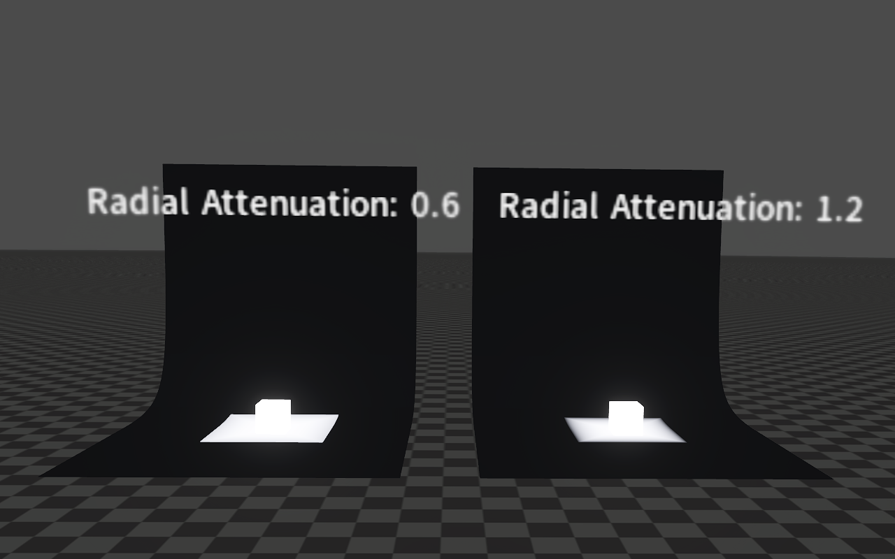
Radial Attenuation
The image below shows the effects of different Radial Attenuation when both Constant Attenuation are 0 and both Linear Attenuation are 0.
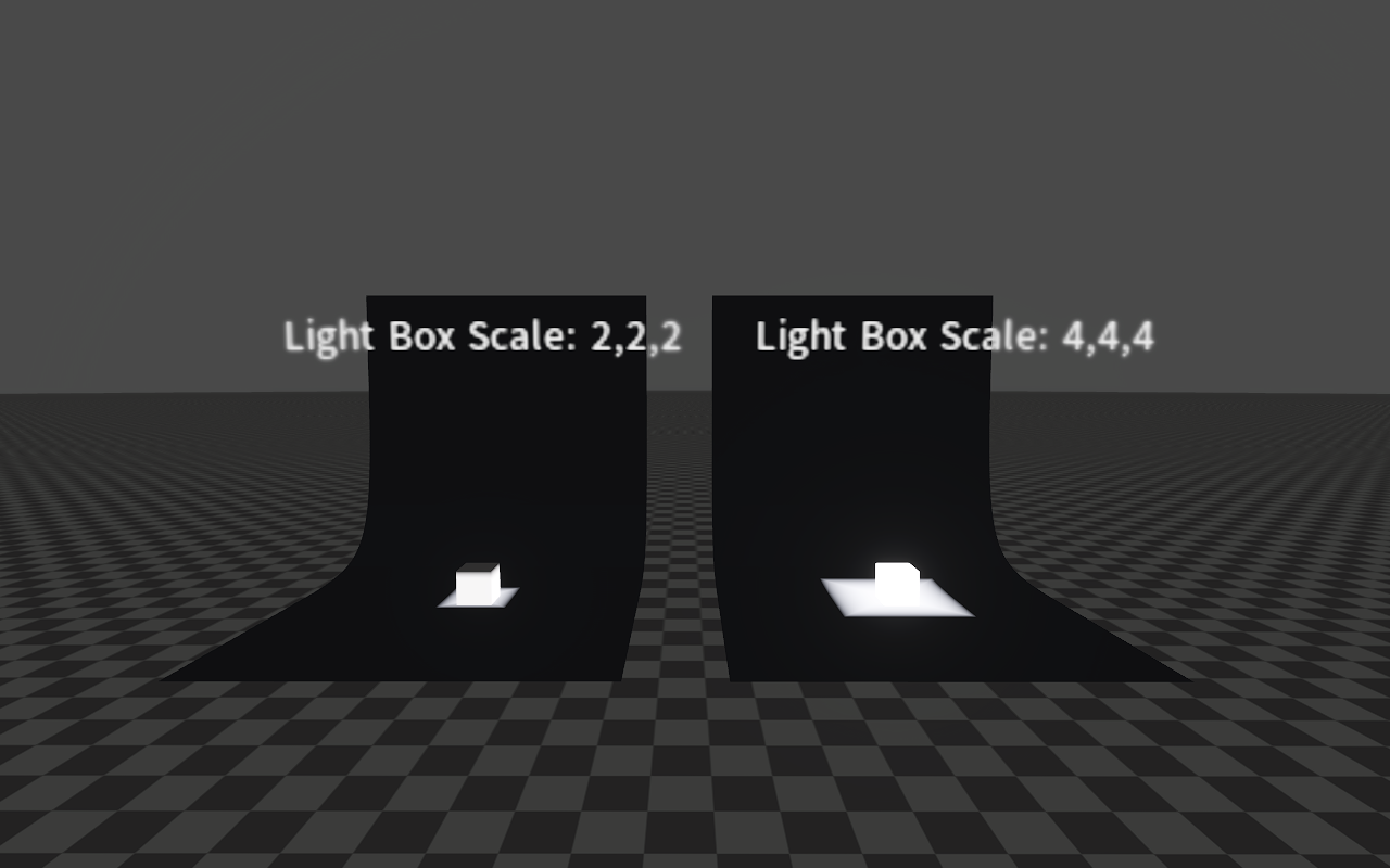
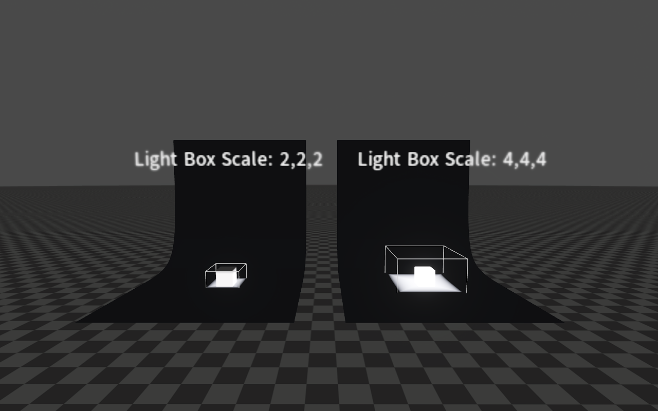
Light Box Scale
Area Light Properties
The following are properties related to the Area Light settings.

| Property | Description |
|---|---|
| Range | Limit the light's visible range. |
| Area Height | Length of the Area Light along the local Y-axis. |
| Area Width | Length of the Area Light along the local Z-axis. |
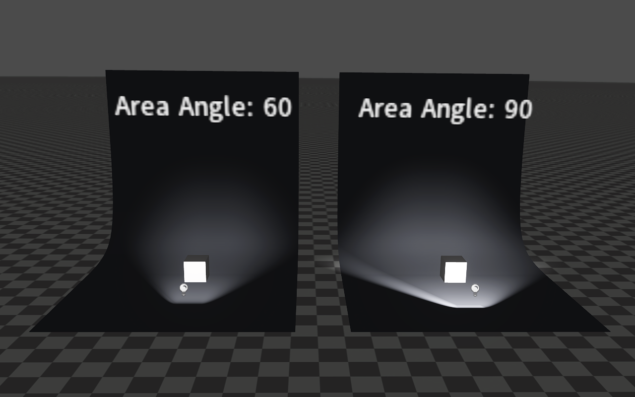
| Area Angle | Illuminated area angle. |
| Shadow Map Size | The size of the shadow map displayed when creating a shadow. |
| Adapt Shadow Map Size | When enabled, the shadow map size can be automatically adjusted according to the view distance. |
Property Effects
Range
The Range property is used to adjust the area illuminated by the light.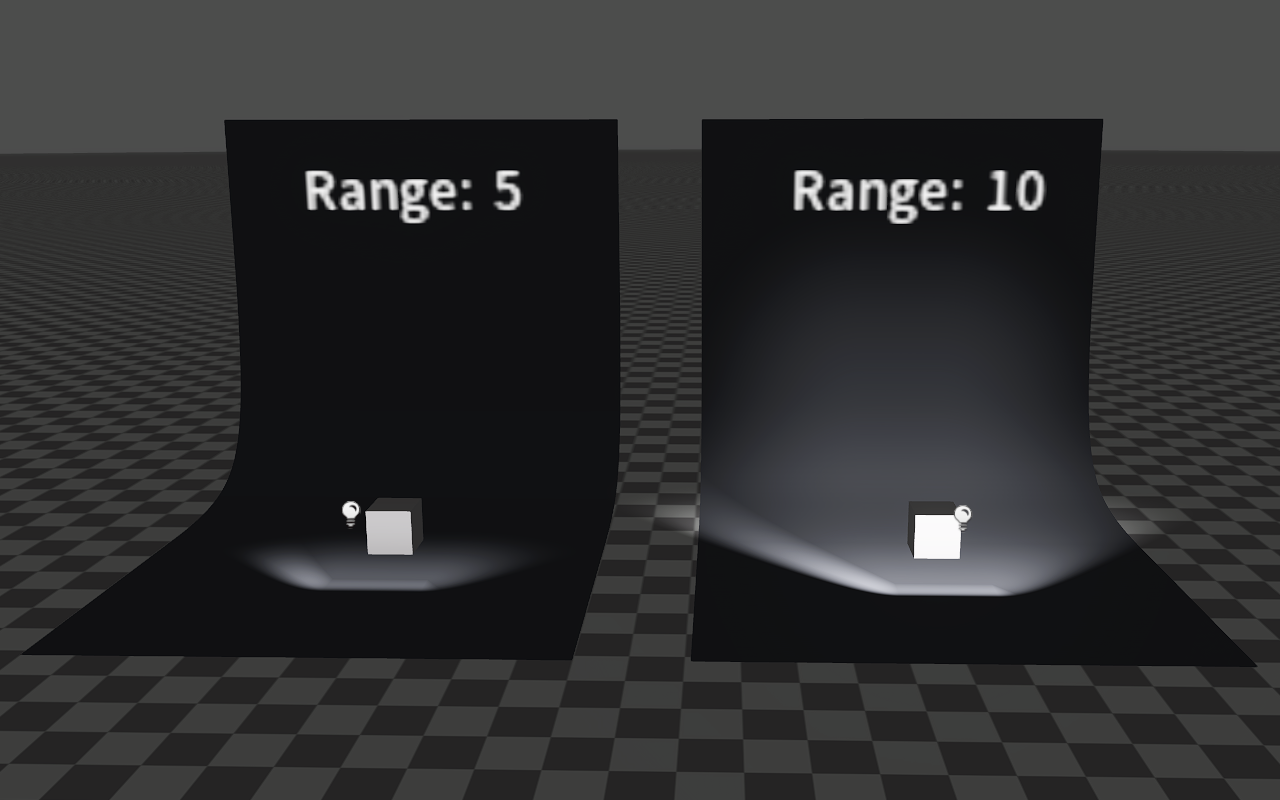
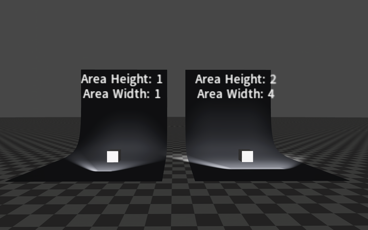
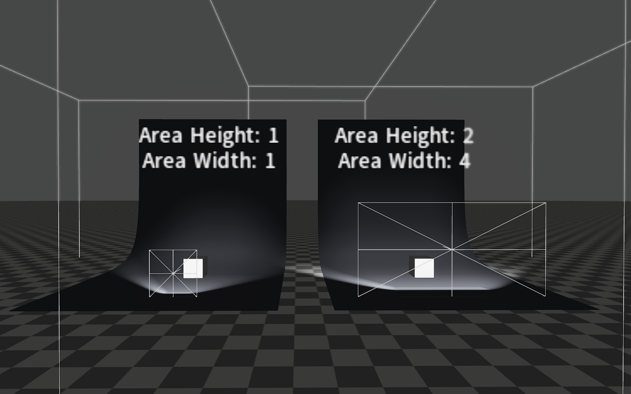
Area Height/Area Width
You can adjust the size of the Area Light with properties Area Height and Area Width.
Area Angle
Shadow Settings
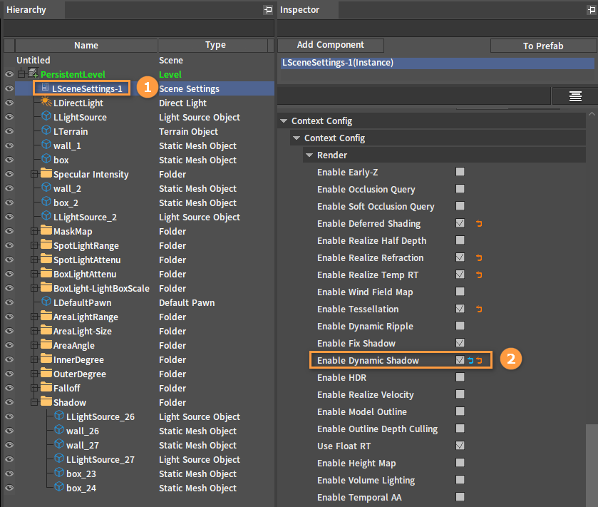
Select LSceneSettings-1 in the Hierarchy panel and check Enable Dynamic Shadow under Context Config.
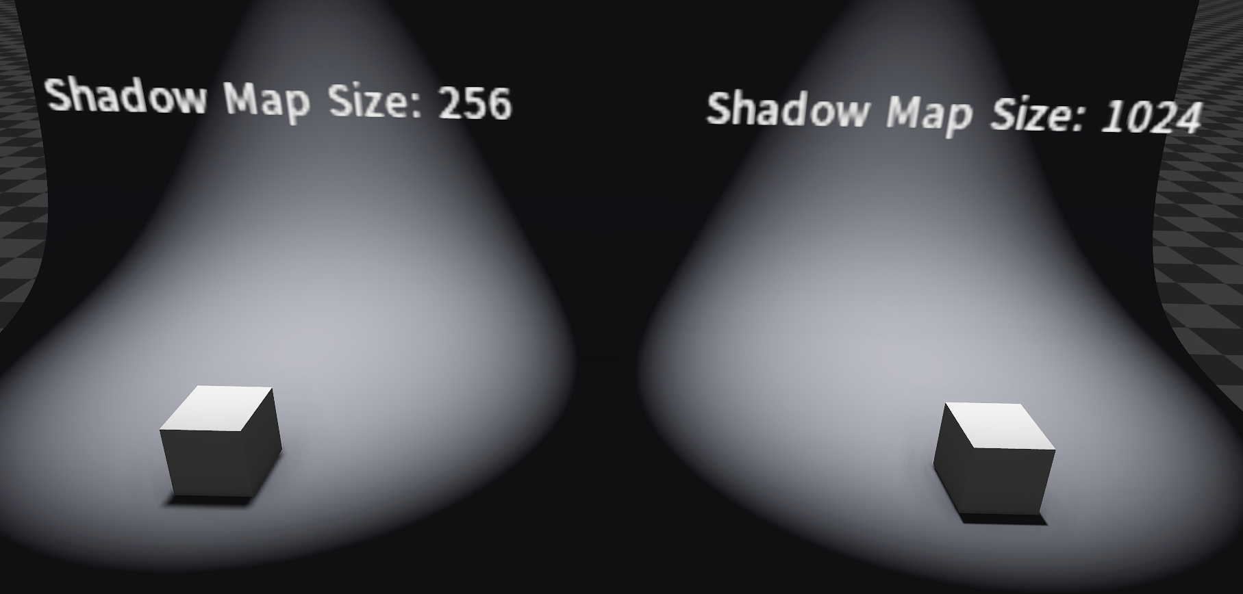
The Shadow Map Size value (should be greater than 0) is required to be set when Point Lights, Spot Lights or Area Lights use shadows. After enabling Adapt Shadow Map Size, the Shadow Map Size value will not be used, and the shadow map size will be calculated automatically. At this time, the Shadow Map Size value should be greater than 0 too.
Disable Adapt Shadow Map Size and set different Shadow Map Sizes. The effects are shown below:
The following are the effects of disabling and enabling Adapt Shadow Map Size when illuminated by an Area Light with a Shadow Map Size of 1024.
Adapt Shadow Map Size Disabled:
Adapt Shadow Map Size Enabled:
Models under moving lights have their shadows move with the models in real time by default. This feature can be disabled via State -> Shadow Map Dynamic property.
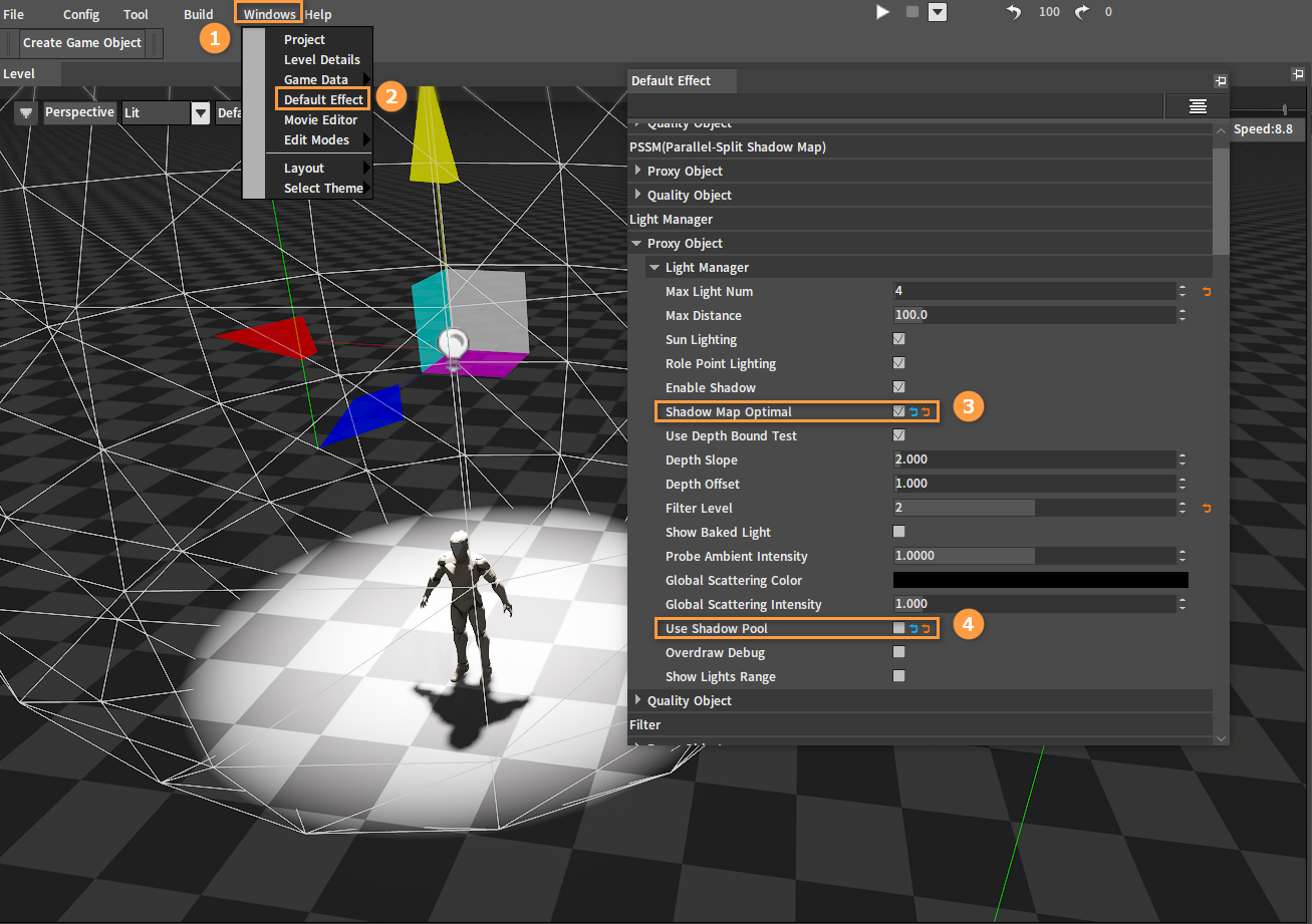
Before you use Shadow Map Dynamic, click Windows -> Default Effect, then in the Default Effect window, check the Shadow Map Optimal property and uncheck Use Shadow Pool under Light Manager.
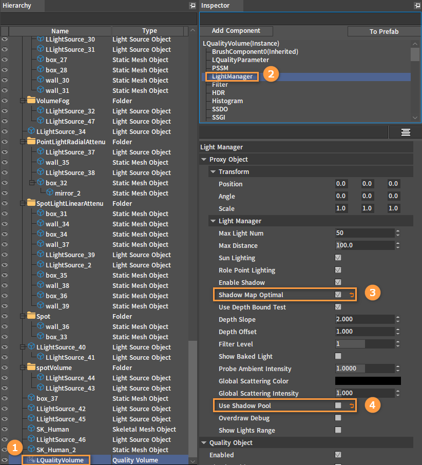
If there is LQualityVolume in the scene, you can directly select LQualityVolume, then select LightManager in the Inspector panel, check Shadow Map Optimal property and uncheck Use Shadow Pool.
At this time, if you uncheck Shadow Map Dynamic and move the model, the shadow will not move with the model. The effect is as shown below:
If you check Shadow Map Dynamic and move the model, the shadow will move with the model. The effect is as shown below:
