Rigidbody Editor
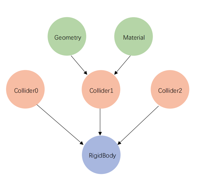
The Rigidbody hierarchy in this documentation is shown as follows:
Overview
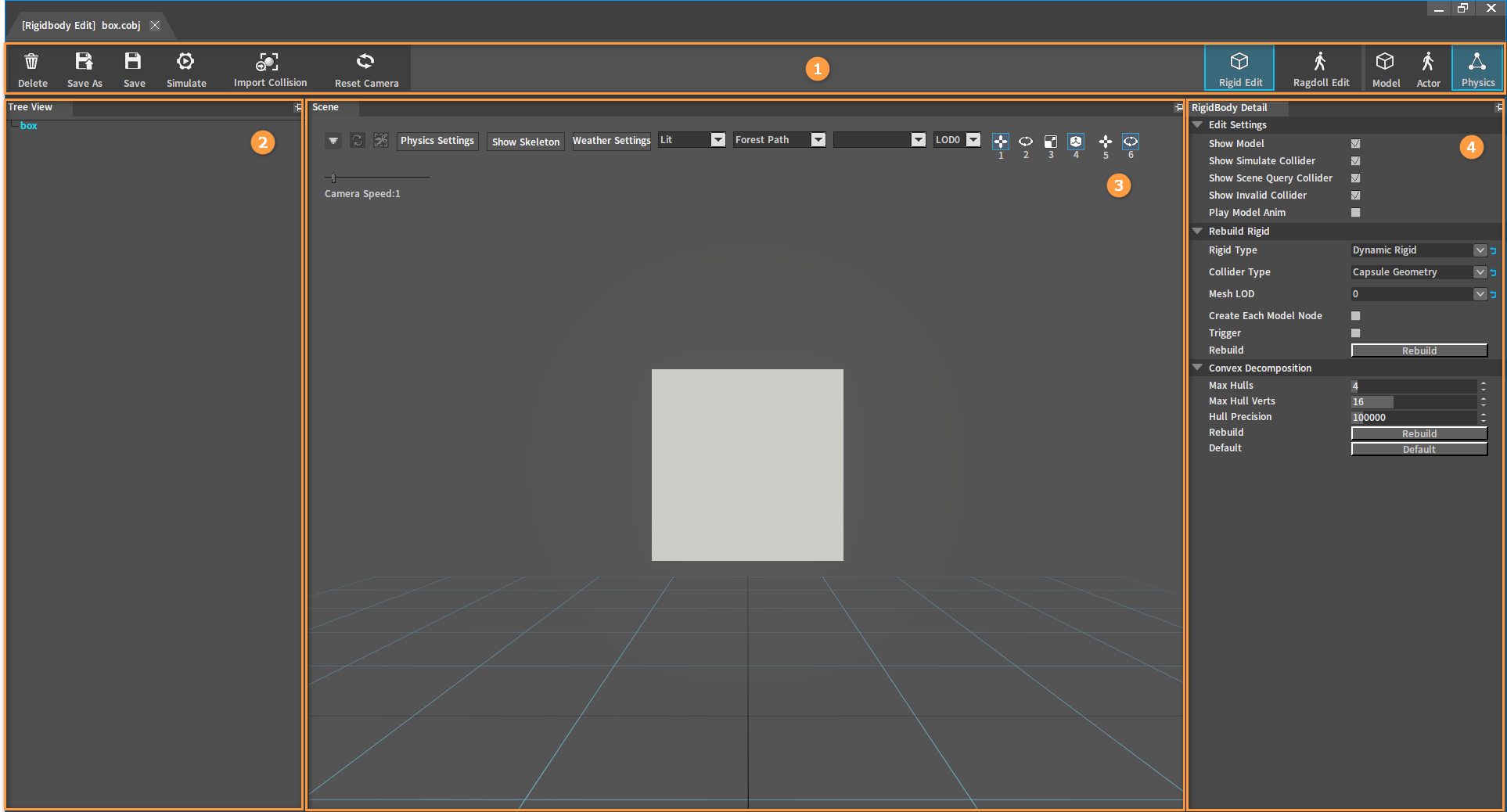
The Rigidbody Editor is used to produce models‘ Rigidbody resources whose physics effects can be edited and debugged.
| No. | Name | Description |
|---|---|---|
| 1 | Top Toolbar | Provide features of deleting, saving, simulating Rigidbodies, importing physics collisions and resetting camera positions. |
| 2 | Tree View Panel | To display Rigidbodies and Collider nodes contained in them, add and delete Colliders. |
| 3 | Scene Panel | To display the models, observe the effect of Rigidbody simulation, and edit the Position, Rotation, Scale of the Colliders. |
| 4 | RigidBody Detail Panel | To edit the properties of the Rigidbodies. |
File Types Available for Rigidbody Editing
| Suffix | Description |
|---|---|
| .xmod | Model resource file. |
Rigidbody File Types Saved by the Editor
The Editor will output Rigidbody resources in the following two formats after saving the Rigidbody editing.
| Suffix | Description |
|---|---|
| .cobj | Rigidbody configuration file in INI format. Save the physics material file path, collision presets, etc. referenced by the Rigidbody. |
| .nxx | Rigidbody configuration file in XML format. Save all properties related to Rigidbody collision and simulation. |
Shortcut Keys
| Shortcut Key | Description |
|---|---|
| 1 | Drag to edit coordinate axis to modify the Position of the selected Collider. |
| 2 | Drag to edit coordinate axis to modify the Rotation of the selected Collider. |
| 3 | Drag to edit coordinate axis to modify the Scale of the selected Collider. |
| 4 | Switch local/world space editing. |
| 5 | Select the blank position of the Scene and drag to change the height of the model. |
| 6 | Select the blank position of the Scene and drag to change the rotation of the model. |
| Shift | Finer adjustments can be made to the position change of the Collider by pressing Shift during dragging to edit the coordinate axis. |
| Ctrl + S | Save the currently edited Rigidbody. |
| Delete | Delete the currently selected Collider. |
| F | Fire a dynamic Rigidbody sphere at the mouse pointer location. |
Opening Rigidbody Editor
Method One
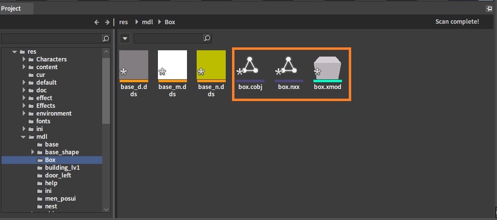
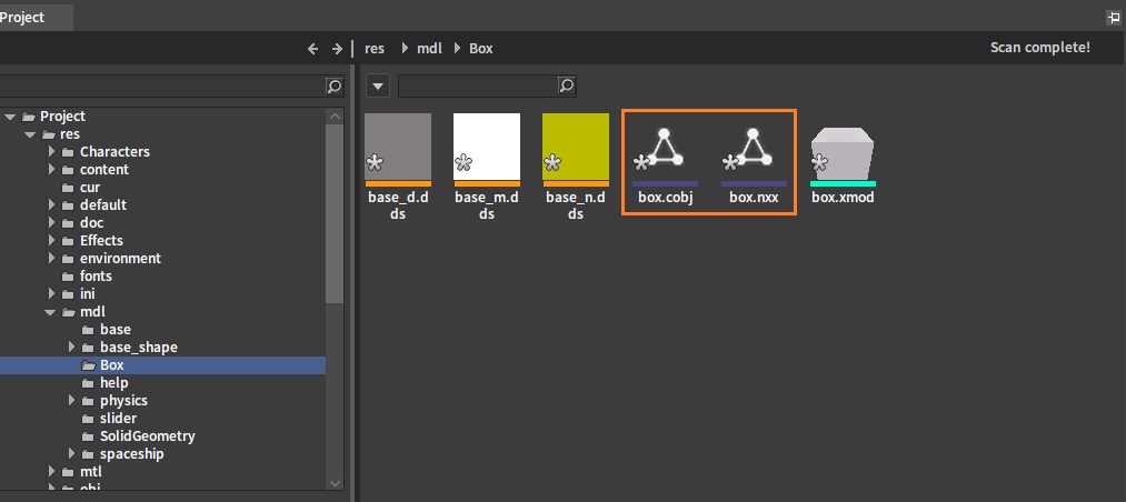
Find the model file or Rigidbody file in the Resource Preview window.
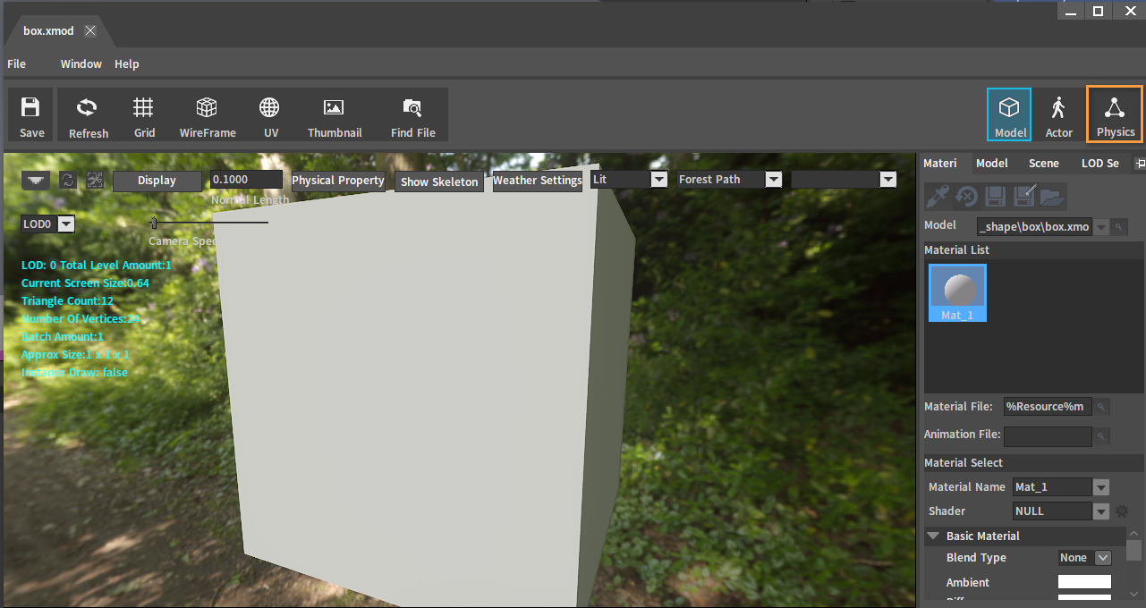
Double-click the model file  to open the Model Editor.
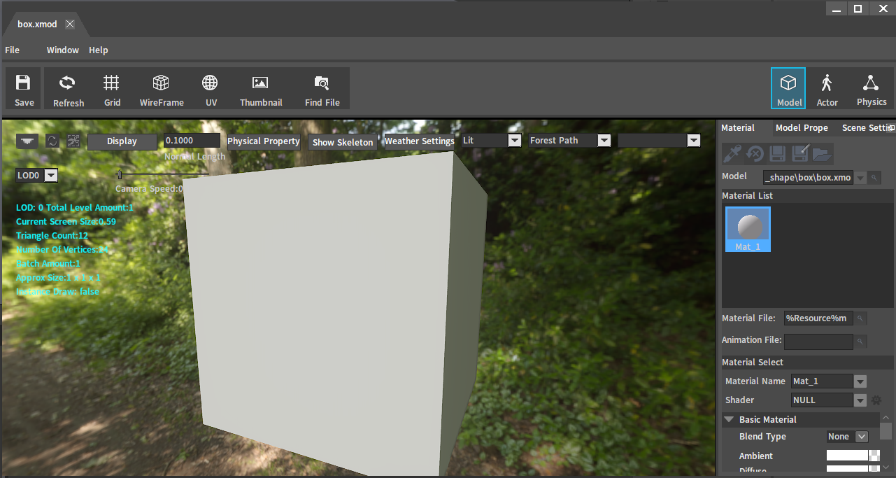
Click the  button in the Model Editor to switch to Rigidbody editing.
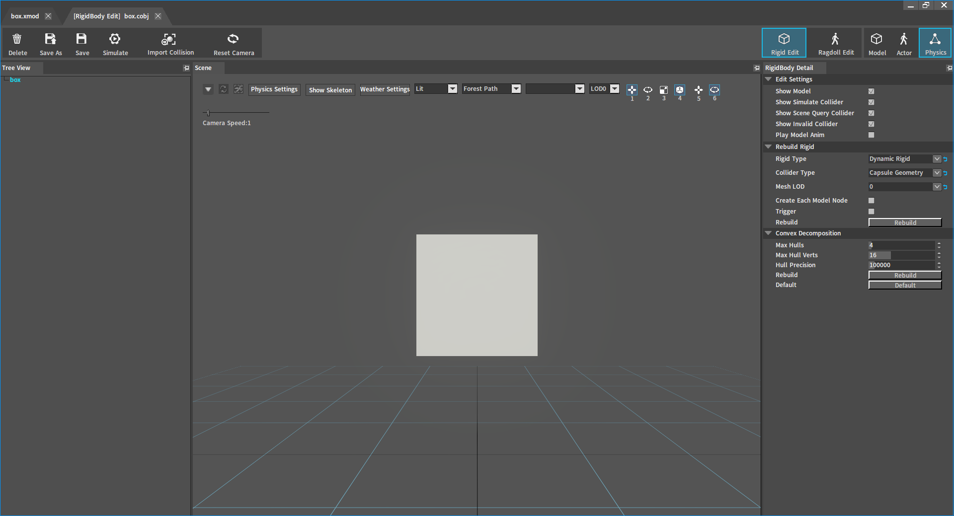
Rigidbody Editor:
Method Two
Double-click any type of Rigidbody file (.cobj/.nxx/.nxb) in the Resource Preview window to open the Rigidbody Editor.
Creating Rigidbodies
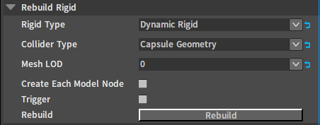
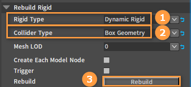
Click the blank space in the Scene panel and find the Rebuild Rigid option in the RigidBody Detail panel.
| Property | Description |
|---|---|
| Rigid Type | Type of the newly created Rigidbody.
|
| Collider Type | Geometry type of the newly created Rigidbody.
|
| Mesh LOD | Select the LOD of the vertex data referenced by the generated collider. |
| Create Collider Per Model Node | When enabled, a collider will be generated separately based on the mesh vertices of each model node in the model. Otherwise, a collider will be generated based on the overall mesh vertices. |
| Trigger | Create as trigger Rigidbody. |
| Rebuild | Rebuild the Rigidbody. |
Select the required Rigid Type and Collider Type under the Rebuild Rigid option, then click the Rebuild button.
Sort the above collider types in descending order of performance or collision precision:
| Sorted By | |
|---|---|
| Performance | Sphere Geometry > Capsule Geometry > Box Geometry > Convex Mesh Geometry > Triangle Mesh Geometry |
| Collision Precision | Triangle Mesh Geometry > Convex Mesh Geometry > Sphere Geometry = Capsule Geometry = Box Geometry |
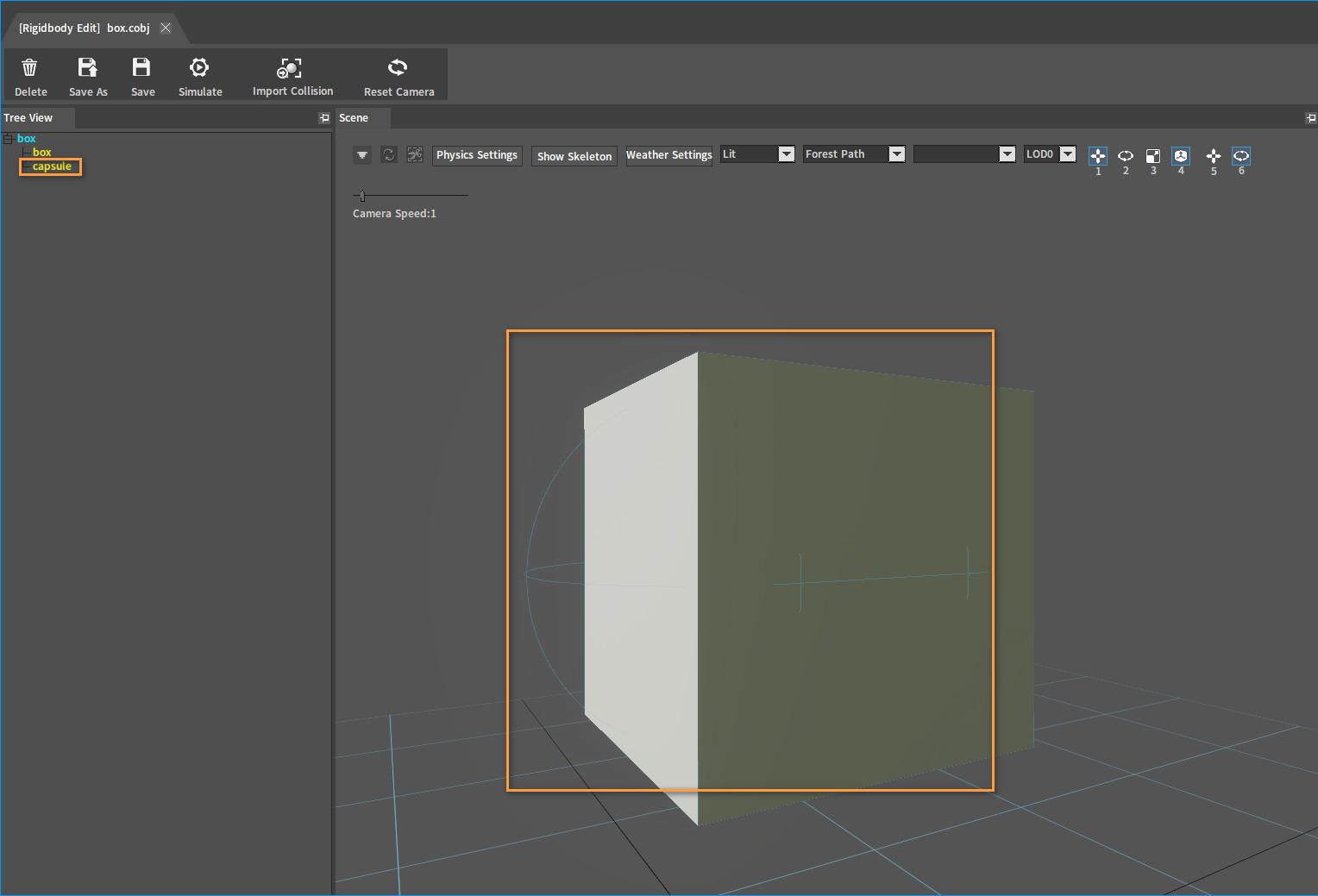
Two tree nodes of different colors will be displayed in the Tree View panel on the left after creation.

| Node | Description |
|---|---|
| Blue box | Rigidbody node. |
| Yellow box | Collider node. |
Adding Colliders
Multiple different Colliders can be added to a Rigidbody.
Select the Rigidbody node in the Tree View panel. Right-click the node and select Add Collider.

Click OK to complete after setting the parameters in the pop-up window. The Create From Model Nodes list displays the Model nodes of the current model. Each Model node contains a set of model vertex data, and you can select any of them to create Rigidbody Colliders.
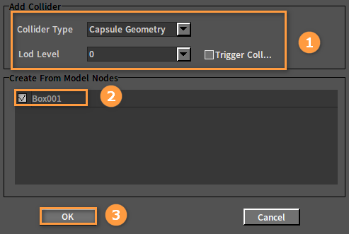
The newly attached Collider can be viewed in the Tree View panel and Scene panel after adding.
Deleting Colliders
Delete unwanted Colliders in Rigidbodies.
Method One
Select the Collider node to be deleted in the Tree View panel. Right-click it and select Delete Collider. Then click the OK button in the pop-up window to delete the selected Collider.

Method Two
Select the Collider to be deleted in the Scene panel, press the shortcut key Delete, and then click the OK button in the pop-up window to delete the selected Collider.
Editing Colliders
Edit the Collider to adjust its position, rotation and scaling, as well as the position and rotation of the model.
Switching Editing Modes of Coordinates
Select the Collider in the Scene panel to display the editing coordinates.
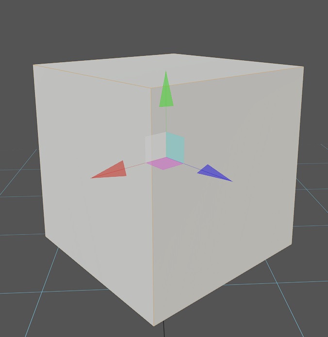
Click the buttons in the Scene panel to switch the editing mode of the coordinates.
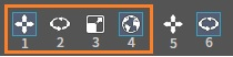
Or press the corresponding Shortcut Keys (1/2/3/4) to switch the editing mode of the coordinate.
| Shortcut Key | Description |
|---|---|
| 1 | Drag the coordinate to change the position of the Collider. |
| 2 | Drag the coordinate to change the rotation of the Collider. |
| 3 | Drag the coordinate to change the scaling of the Collider. |
| 4 | Switch between the local and world spatial coordinate systems. |
| Shift | Hold down the Shift key and drag to modify the position/rotation/scaling of the Collider more precisely. |
Adjusting the Position and Rotation of Models
When the cursor is placed at a blank space of the Scene panel, in panning mode, click and drag the mouse up or down to move the model up or down ; And in rotation mode, click and drag the mouse left or right to rotate the model left or right.
Click the buttons in the Scene panel to switch the editing mode of the model.
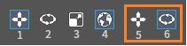
Or press the corresponding Shortcut Keys (5/6) to switch between the translation or rotation mode of the model.
| Shortcut Key | Description |
|---|---|
| 5 | Translate the model up or down. |
| 6 | Rotate the model left or right. |
Editing Properties of Rigidbodies
By editing different properties of the Rigidbody, you can get different physics effects in the physics simulation.
In the Tree View panel, select the Rigidbody to be edited. The RigidBody Detail panel on the right shows settings for the properties of the Rigidbody.
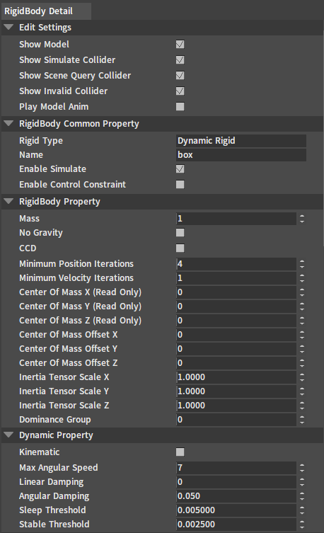
Edit Settings

| Property | Description |
|---|---|
| Show Model | Used to hide the model to observe the Rigidbody collision. |
| Show Simulate | Used to switch on/off information on the geometry involved in the physics simulation. |
| Show Scene Query | Used to switch on/off information on the geometry involved in the scene collision query. |
| Show Invalid Collider | Used to switch on/off the display of information of the geometry that does not participate in the simulation or the collision detection. |
| Play Model Anim | Used to play/stop the model animation. |
Rigidbody Common Properties

| Property | Description |
|---|---|
| Rigid Type | The type of the Rigidbody. |
| Name | The name of the Rigidbody. |
| Enable Simulate | Specify whether the Rigidbody will participate in the physics simulation or not. If Enable Simulate is false, then the Rigidbody will not participate in the physics simulation. This means there will be no collisions with other objects involved in the simulation, and the position of the model will not be controlled by physics. This setting does not affect the Rigidbody being detected by the scene collision query. |
| Enable Control Constraint | Create a joint to constrain the motion of the Rigidbody (only available in ragdoll editing) . |
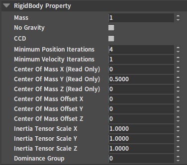
Rigidbody Properties
| Property | Description |
|---|---|
| Mass | Mass of the Rigidbody in Kg. When the value is set too small or 0, the simulation will experience jitter or penetration. |
| No Gravity | When No Gravity is true, the Rigidbody will no longer be affected by the gravity of the scene. |
| CCD | Continuous collision detection. When the Rigidbody is moving too fast, causing something like a tunnel effect and penetrating other Rigidbodies, you need to enable this option. |
| Minimum Position Iterations | This property defines the resolution accuracy when the Rigidbody is controlled by constraints. If the Rigidbody is controlled by constraints and jitter and other abnormal performance occurs, the number of position iterations can be increased appropriately to make the Rigidbody more stable. |
| Minimum Velocity Iterations | This property defines the resolution accuracy of the Rigidbody when in a collision. If the bounce of the two colliding objects is too violent, the number of velocity iterations can be increased appropriately. This will make the separation velocity of the two objects approach the result defined by the material elastic coefficient. |
| Center Of Mass X/Y/Z (Read Only) | This is a read-only property that shows the position of the Rigidbody's mass center in local space. |
| Center Of Mass Offset X/Y/Z | Used to offset the coordinates of the Rigidbody's mass center. |
| Inertia Tensor Scale X/Y/Z | The original inertia coefficient of the Rigidbody is related to the mass and the position of the Rigidbody's mass center. This coefficient is scaled from the original inertia coefficient of the Rigidbody. The larger the inertia, the less likely the state of motion will change. |
| Dominance Group | Currently, dominance groups from 0 to 10 are defined. Dominance relationships exist between dominance groups from 1 to 10, and the larger the number, the higher the dominance level. Group 0 has the same dominance level as all other groups. Rigidbodies with higher dominance levels have infinitely large mass relative to those with lower levels. |
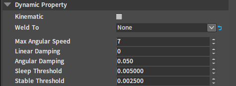
Dynamic Properties
| Property | Description |
|---|---|
| Kinematic | If Kinematic is true, the current Rigidbody type will switch to kinematic Rigidbody. If Kinematic is false, the current Rigidbody type will switch to dynamic Rigidbody. |
| Weld To | Weld one ragdoll's bone to another bone. Used to replace the feature of fixing joints (This property is used for ragdoll editing). |
| Max Angular Speed | The maximum angle speed of the Rigidbody will not be larger than this value. |
| Linear Damping | Affect the attenuation rate of the the Rigidbody's linear velocity. The larger the linear damping, the faster the Rigidbody will stop its linear motion. |
| Angular Damping | Affect the attenuation rate of the the Rigidbody's angular velocity. The larger the angular damping, the faster the Rigidbody will stop rotating. |
| Sleep Threshold | This is a Rigidbody kinetic energy threshold. When the Rigidbody kinetic energy is below this value, the Rigidbody starts the sleep timer and enters sleep state at the end of the timer. |
| Stable Threshold | When the mass-normalized kinetic energy of the Rigidbody is below this threshold, the object will tend to stabilize. The stability here refers to the stability of the interactions among a large number of objects in the scene. |
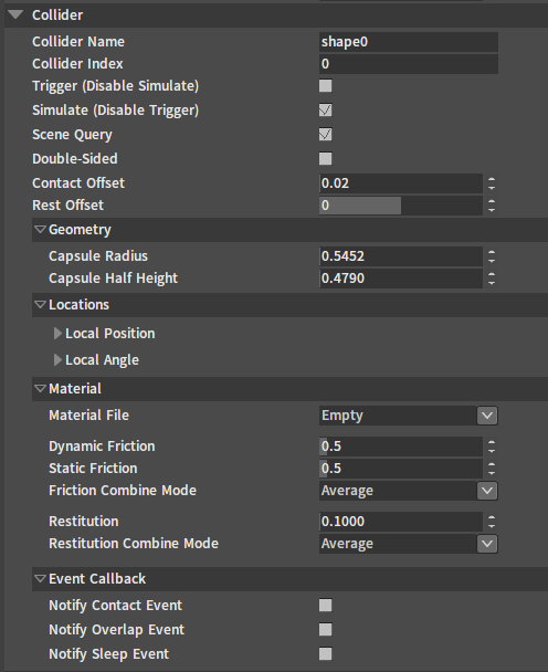
Editing Collider Properties
In the Scene panel or Tree View panel, select the Collider you want to edit. The corresponding property settings will be displayed in the RigidBody Detail panel on the right.
| Property | Description |
|---|---|
| Collider Name | Name of Collider. |
| Collider Index | Index of Collider. |
| Trigger (Disable Simulate) | When the Trigger (Disable Simulate) is true, the Collider is converted to a trigger Collider, a trigger event will be generated when there are other Colliders inside the trigger Collider. |
| Simulate (Disable Trigger) | Collider participates in physical simulation. |
| Scene Query | Collider participates in scene collision query. |
| Double-sided | Effective only when the Collider type is Triangle Mesh Geometry . The double-sided mesh can detect the surface normal of the back triangle when performing scene collision queries inside the mesh. |
| Contact Offset | When the distance between two Colliders is less than the Contact Offset, two objects will collide. Contact Offset must be greater than Rest Offset. |
| Rest Offset | The rest distance of two Colliders is equal to the sum of their Rest Offset. When Rest Offset equals to 0, two objects will just stick together. When Rest Offset is greater than 0, two objects can slide more smoothly into each other, because this minimizes the effect of irregular surfaces during sliding. |
Geometries
This setting is displayed only if the Geometry Type is Capsule Geometry, Sphere Geometry, or Box Geometry, and the Geometry display different properties depending on the Geometry Type.
Capsule Geometries

| Property | Description |
|---|---|
| Capsule Radius | Radius of capsule. |
| Capsule Half Height | Half height of capsule. |
Sphere Geometries
![]()
| Property | Description |
|---|---|
| Sphere Radius | Radius of sphere. |
Box Geometries

| Property | Description |
|---|---|
| Box Length (X) | Length of box. |
| Box Width (Y) | Width of box. |
| Box Height (Z) | Height of box. |
Locations

| Property | Description |
|---|---|
| Local Position | The Position of the Collider in the local space of the Rigidbody. |
| Local Angle | The Angle of the Collider in the local space of the Rigidbody. |
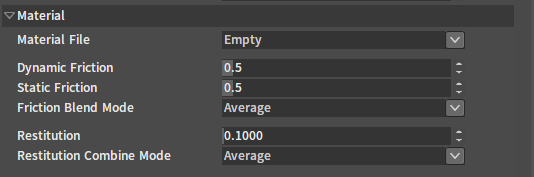
Materials
| Property | Description |
|---|---|
| Material File | Physical material file path. The Collider will apply the material properties specified in the physical material file. If no physical material file is specified, the Collider will apply the following material properties. |
| Dynamic Friction | Coefficient of dynamic friction. |
| Static Friction | Coefficient of static friction. |
| Friction Combine Mode | Friction Combination mode. |
| Restitution | Coefficient of elasticity. |
| Restitution Combine Mode | Elastic coefficient combination mode. |
Friction/Restitution Combine Mode
After two objects of different materials collide, the blending mode of the larger object number becomes the effective combine mode between the two objects.
finalCombineMode = maximum(material0.combineMode, material1.combineMode)
| Serial Number | Name | Description |
|---|---|---|
| 1 | Average | (a + b) / 2 |
| 2 | Min Value | minimum(a,b) |
| 3 | Multiply | a * b |
| 4 | Max Value | maximum(a,b) |
Event Callbacks

| Property | Description |
|---|---|
| Notify Contact Event | Whether a contact event is triggered when a Rigidbody collides with other object. |
| Notify Overlap Event | Whether an overlap event is triggered when a Rigidbody overlaps another object. The collision results between the two objects must both be overlap for the overlap event to be successfully triggered. |
| Notify Sleep Event | Whether a sleep event is triggered when the Rigidbody falls into sleep or is awakened. |
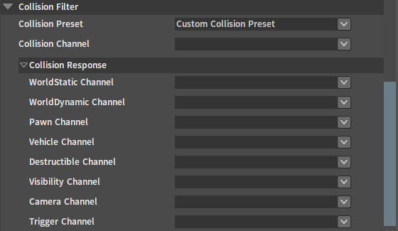
Collision Filters
| Property | Description |
|---|---|
| Collision Preset | Collision preset name. |
| Collision Channel | Channel of collision. |
| Collision Response | Collision response to other collision channel types. |
Saving/Deleting/Simulating Rigidbodies
The Top Toolbar provides corresponding button features.

| Button Name | Description |
|---|---|
| Delete | Empty the edited Rigidbody and delete the resource files. |
| Save As | Save the currently edited Rigidbody as. |
| Save | Save the currently edited Rigidbody. |
| Simulate | Simulate the currently edited Rigidbody. |
Convex Decomposition
Click the blank space in the Scene panel to see the related properties of Convex Decomposition in the RigidBody Detail panel. Too many convexes and too high decomposition precision will strongly affect the speed of collision generation.

| Property | Description |
|---|---|
| Max Hulls | The maximum number of convex hulls that can be generated for each mesh in the model. |
| Max Hull Verts | The maximum number of vertices that can be generated for each decomposed convex hull. |
| Hull Precision | The precision of the generated convex vertices. The larger the value, the more precise the generated convex. |
| Rebuild | Generate a collision based on the current settings. |
| Default | Restore default settings. |