Ragdoll Editor
Overall
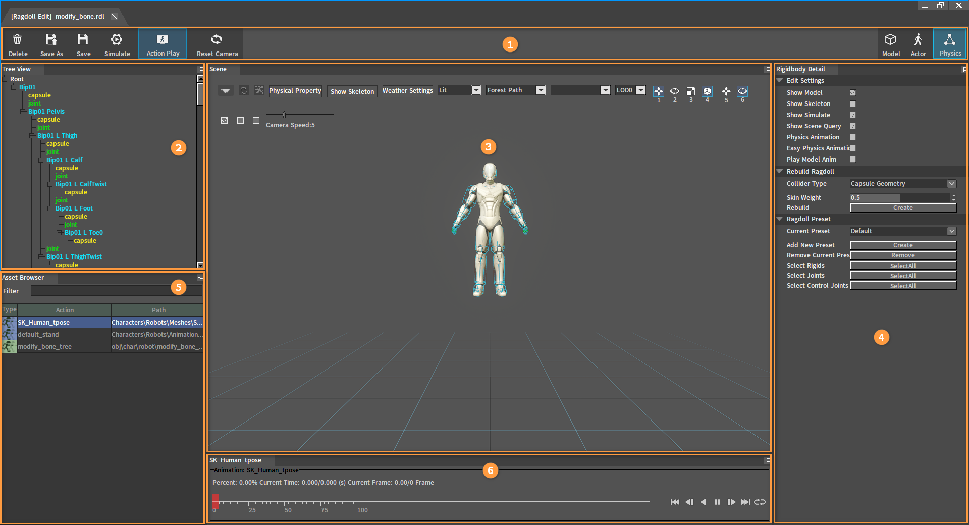
The Ragdoll Editor is used to produce ragdoll resources for models and skeletal animation models. Ragdolls can create individual collisions for each bone of the animation character and can also be used to achieve dynamic simulation effects that conform to human or animal joint constraint as well as physics animation effects.
| No. | Name | Description |
|---|---|---|
| 1 | Top Toolbar | Provide functions to delete, save, simulate ragdolls, and to open the animation playback window. |
| 2 | Tree View panel | Used to display the full skeleton tree structure of the animation character; Provide editing-friendly selection functions such as single selection, multiple selection, box selection, full selection, etc. ; Provide menu functions for creating and deleting Rigid Bodies/joints. |
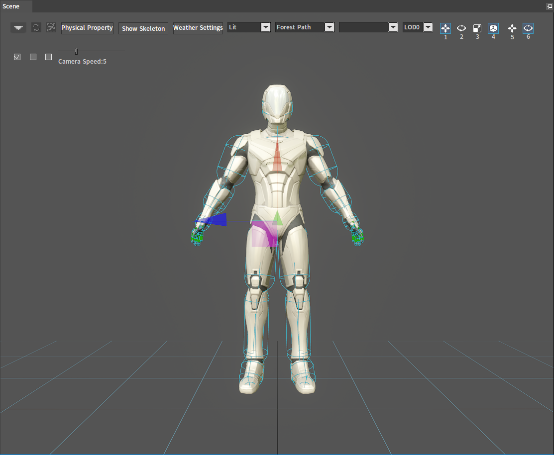
| 3 | Scene panel | Used to display the skeletal animation model and observe the simulation effect; Provide editing functions such as displacement, rotation, scaling, etc. for Rigid Bodies/joints; Provide auxiliary functions for easy editing and debugging of ragdoll effects. |
| 4 | Rigidbody Detail panel | Provide editing functions including editing and setting properties of Rigid Bodies/joints and other objects. |
| 5 | Asset Browser panel | Display the playable action list of the current animation character. |
| 6 | Animation playback control panel | Provide action playback control function. |
File Types Editable for the Ragdoll
| Suffix | Description |
|---|---|
| .xmod | Model resource files |
| .actor | Skeletal animation resource files |
Editing the Saved Ragdoll File Types
After saving the ragdoll edits, the Editor will output ragdoll resources in the following 2 formats.
| Suffix | Description |
|---|---|
| .rdl | Rigid body configuration files in XML format. Information on the ragdoll preset, the collision preset used by each bone, etc. is saved in this file. |
| .rlx | Rigid body configuration files in XML format. Properties of all Rigid Bodies and joints are saved in this file. |
Top Toolbar

| Name | Description |
|---|---|
| Delete | Delete the currently saved ragdoll resource. |
| Save As | Save the currently edited ragdoll as another ragdoll configuration with a user-specified name. |
| Save | Save the current ragdoll's edits. |
| Simulate | Start or end the ragdoll simulation. |
| Action Play | Turn on/off the animation playback control panel. |
| Reset Camera | Return the camera to the initial position. |
Tree View Panel
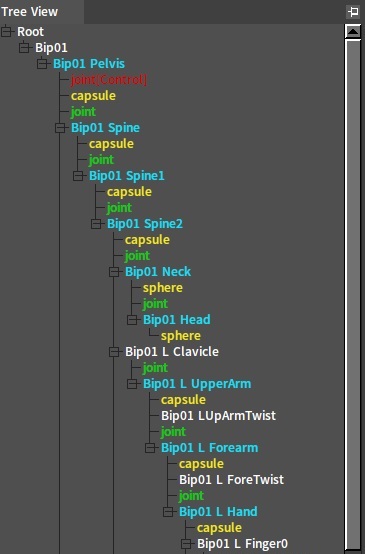
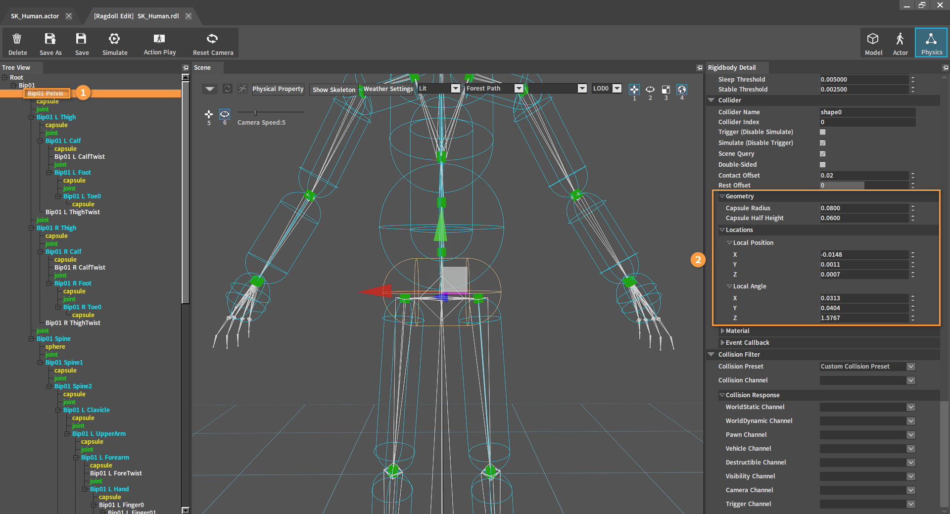
In the Tree View panel, different colors represent different tree node types.
| Node | Description |
|---|---|
| Bip01 Pelvis | Bone Nodes The name of the Bone Node is the same as the name of the bone in the skeletal animation. Bone Nodes with Rigid Bodies created are marked in blue (later this tree node type is called Rigid Body Node), otherwise marked in white. |
| capsule | Collider Nodes Collider Nodes contains geometry information and physics material information. Collider Nodes are marked in yellow. |
| joint | Joint Nodes Joint Nodes are used to constrain the relative motion between two Rigid Bodies. Joint Nodes are marked in green. |
| joint(Control) | Joint Control Nodes The Joint Control Node is a special Joint node. Generally used to constrain the relative movable range between the Rigid Body and the corresponding animation skeleton. Joint Control Nodes are marked in red. |
Panel Operations
| Operation | Description |
|---|---|
| Left-Click | Left-click to select a tree node. Meanwhile, the Rigid Body/joint/Collider object represented by the tree node will be selected in the Scene panel. Properties in the Ridgidbody Detail panel will be refreshed to match the object type. |
| Right-Click | Right-click a tree node to open the operation menu. Selecting different types and numbers of tree nodes will open different menus. |
| Hold Down Ctrl | Hold down the Ctrl key to multi-select tree nodes. Note: The Rigid Body Node and the Joint Node cannot be selected at the same time. |
| Hold Down Shift | Hold down the Shift key to select all tree nodes whose type matches the first selected tree node type between the two selected tree nodes. |
| Ctrl + A | After selecting a tree node, press Ctrl + A to select all child nodes of the same type under that tree node (including the first selected node). |
| Delete | Delete the currently selected Rigid Body, Collider or joint. |
Right-click Menu Items
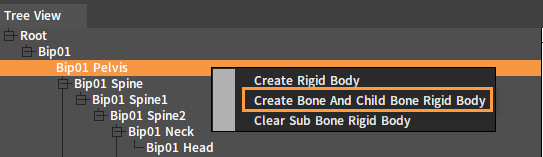
Right-click a Bone Node to open the Shortcut Menu.
| Menu Item | Description |
|---|---|
| Create Rigid Body | Create a Rigid Body for the current Bone Node. |
| Create Bone And Child Bone Rigid Body | Create Rigid Bodies for the currently selected Bone Node and all its child bone nodes. Bone Nodes that have created Rigid Bodies will be skipped. |
| Clear Sub Bone Rigid Body | Clear the Rigid Bodies of all child nodes under the current Bone Node. |
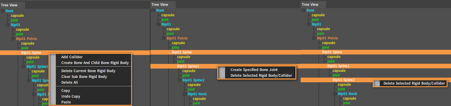
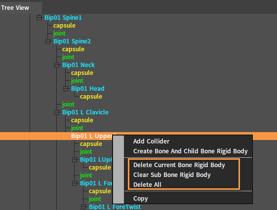
Right-click a Rigid Body Node to open the Shortcut Menu.
| Menu Item | Description |
|---|---|
| Add Collider | Add a new Collider to the Rigid Body. |
| Create Bone And Child Bone Rigid Body | Create Rigid Bodies for the currently selected bone and all its child bone nodes. Bone Nodes that have created Rigid Bodies will be skipped. |
| Delete Current Bone Rigid Body | Delete the Rigid Body of the currently selected Bone Node. |
| Clear Sub Bone Rigid Body | Clear the Rigid Bodies of all child nodes under the current Bone Node. |
| Delete All | Delete Rigid Bodies of the current Bone Node and its child nodes. |
| Copy | Copy properties of the current Rigid Body Node, including properties of the Rigid Body and all its colliders. Note: This option appears when the Rigid Body Node is selected singly. |
| Undo Copy | Undo copying properties of the Rigid Body Node. |
| Paste | Paste the previously copied Rigid Body properties to the currently selected Rigid Body Node. Note: This option appears when the Rigid Body Node has been copied. |
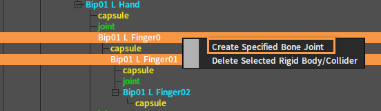
| Create Specified Bone Joint | Create joints for the two selected Rigid Body Nodes. Note: This option appears when two Rigid Body Nodes are selected. |
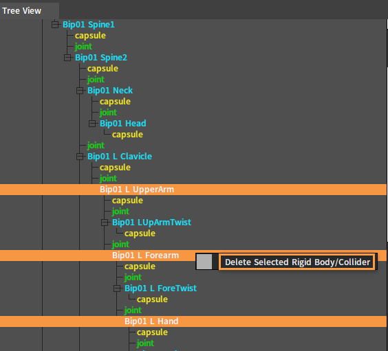
| Delete Selected Rigid Body/Collider | Delete all selected Rigid Body Nodes or Collider Nodes. Note: This option appears when multiple Rigid Body Nodes are selected. |
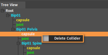
Right-click a Collider Node to open the Shortcut Menu.
| Menu Item | Description |
|---|---|
| Delete Collider | Delete the selected Collider Node. |
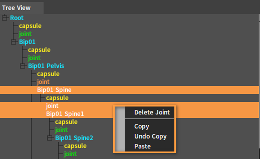
Right-click a Joint Node to open the Shortcut Menu.
| Menu Item | Description |
|---|---|
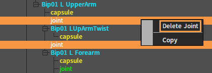
| Delete Joint | Delete all selected Joint Nodes. |
| Copy | Copy properties of the current Joint Node. |
| Undo Copy | Undo copying properties of the Joint Node. |
| Paste | Paste the previously copied joint properties to the currently selected Joint Node. |
Scene Panel
Panel Operations
| Operation | Description |
|---|---|
| Click A Bone Or A Joint | Left-click the position of the Rigid Body/joint to select the object. The editing coordinate axis will appear on the selected Rigid Body/joint, meanwhile, the corresponding tree node will be selected in the Tree View panel and the properties in the Rigidbody Detail panel will be refreshed to match the selected object type. |
| Click The Blank Space In The Scene | Left-click the blank space in the scene and all currently selected Rigid Bodies/joints/coordinate axes will be cleared. The Tree View panel will also clear the selection, and the Rigidbody Detail panel will revert to default settings. |
| Click And Drag Coordinate Axis | Based on the current coordinate's editing mode, drag the axis to modify the position/rotation/scaling of the currently selected Rigid Body/joint. |
| Hold Down Ctrl | Hold down Ctrl to multi-select Rigid Bodies/joints. Note: The Rigid Body and the joint cannot be selected at the same time. |
| Hold Down Shift | When selecting a Rigid Body/joint and dragging the axis to modify its position/rotation/scaling, hold down the Shift key to make the modification more accurate each time. |
| F | Fires a small dynamic rigid sphere towards the position where the mouse is pointing. |
| Delete | Delete the currently selected Rigid Body, Collider or joint. |
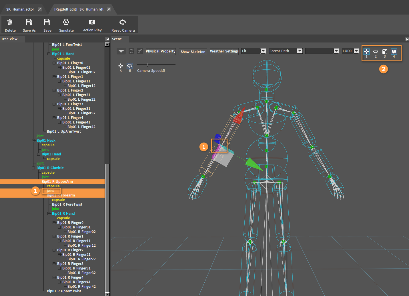
Switching the Coordinate's Editing Modes
![]()
| Shortcut Key | Description |
|---|---|
| 1 | Drag the coordinate axis to modify the position of the selected Collider. |
| 2 | Drag the coordinate axis to modify the rotation of the selected Collider. |
| 3 | Drag the coordinate axis to modify the scaling of the selected Collider. |
| 4 | Switch between local and world spatial editing. |
| 5 | In the black space of the scene, left-click and hold, drag up and down to change the height of the model in the scene. |
| 6 | In the black space of the scene, left-click and hold, drag left and right to change the scaling of the model. |
Modifying the Camera Movement Speed in the Scene
![]()
| Operation | Description |
|---|---|
| Drag Slider | Drag the slider to adjust the camera's movement speed in the scene. |
Property Editing Panel
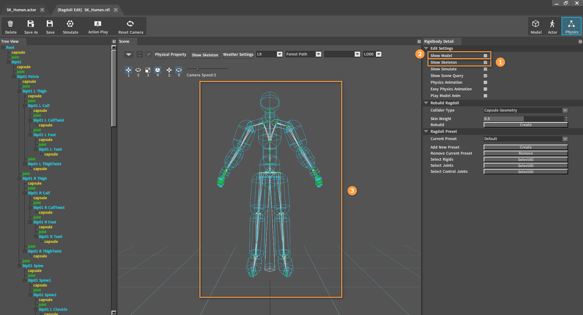
Editing Settings

| Property | Description |
|---|---|
| Show Model | Used to turn on/off model display. |
| Show Skeleton | Used to turn on/off character's skeleton display. |
| Show Simulate | Used to turn on/off the display of information on all the geometries involved in the simulation. |
| Show Scene Query | Used to turn on/off the display of information on all the geometries involved in the scene collision query. |
| Physics Animation | Used to turn on/off the Physics Animation feature for the current animation character. |
| Easy Physics Animation | Used to turn on/off the Easy Physics Animation feature for the current animation character. The physics animation effects may be incorrect due to constraints not fully matching the animation. When Easy Physics Animation == true, physics animation will temporarily ignore the limit of the constraints and get better animation effects. |
| Play Model Anim | Used to turn on/off playback of the model animation. Effective only when the edited object is a model with model animations. |
Other properties in the Edit Settings panel are explained in detail in operation description.
Asset Browser Panel
Action Playlist

| Operation | Description |
|---|---|
| Double-Click List | Switch the currently playing action of the animation character. |
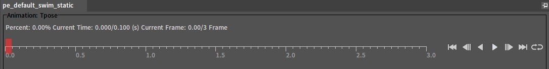
Animation Playback Controller
Drag the red cursor in the animation playback controller to switch the currently playing action of the animation character to the specified frame.
| Button | Description |
|---|---|
| Jump the character action to frame 0. | |
| Return the character action to the previous frame. | |
| Play the action backwards. | |
| Pause the playing action. | |
| Play the action forwards. | |
| Advance the character action to the next frame. | |
| Jump character action to the last frame. | |
| Loop the action. | |
| Single play the action. |
Editing and Operating Instructions
Opening the Editor
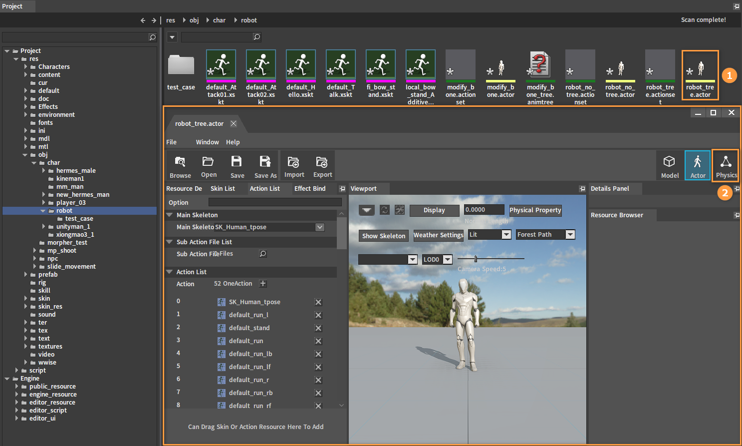
Find the skeletal animation resource file (.actor) that needs creating a ragdoll in the Project panel of the Component Editor. Double-click the file to open the Actor Editor, and click the  button at the top right of the Actor Editor to open the Ragdoll Editor.
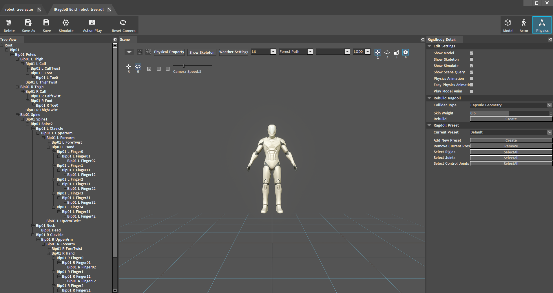
The Ragdoll Editor:
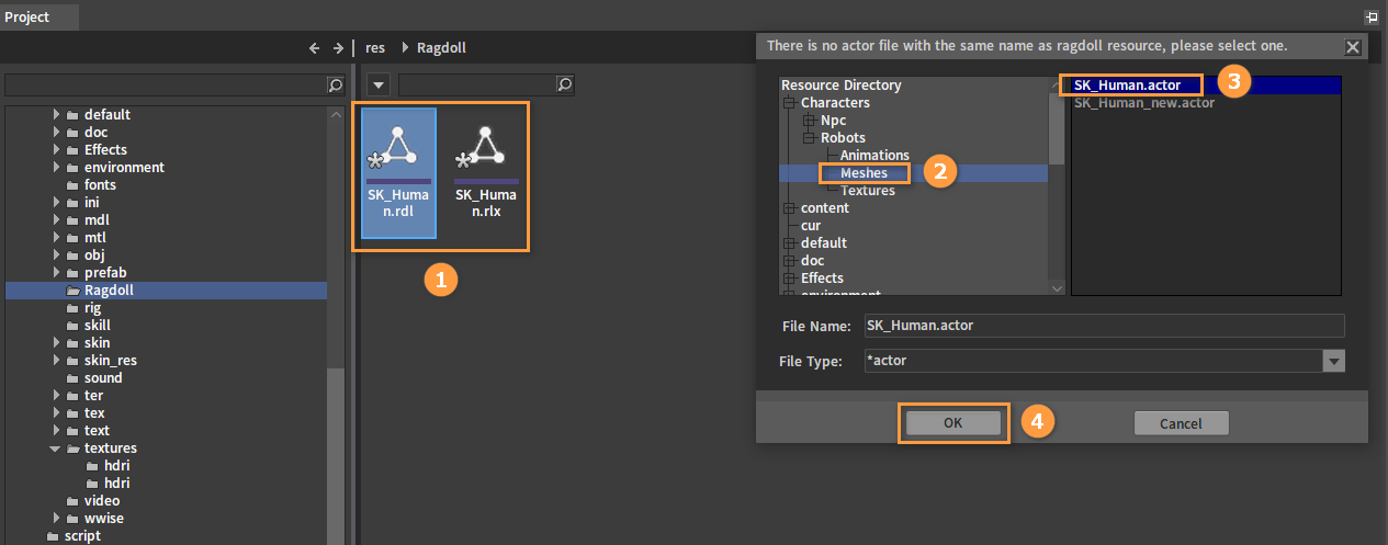
Or find an existing ragdoll file (.rdl and .rlx) in the Resource Preview window, double-click it and select an .actor file to open the Ragdoll Editor.
Creating Ragdolls
If there is a selected Rigid Body or joint in the current Ragdoll Editor, click the blank space in the Scene panel to clear the selection first.
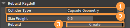
In the Rigidbody Detail panel, find the Rebuild Ragdoll option, set the relevant properties as needed, and click the Create button to rebuild the ragdoll.
| Property | Description |
|---|---|
| Collider Type | Used to define the type of the Collider used by the Rigid Body of the newly created ragdoll. For example, if this property is set to Capsule Geometry, collisions of all ragdoll's Rigid Bodies will be created by the capsule. |
| Skin Weight | When creating a Rigid Body for each bone, information on the skin vertices associated with the bones is collected. Skin Weight defines the threshold of the blend weight of these vertices with the bones, and vertices with blend weight larger than the threshold will be involved in creating the Rigid Body. |
| Rebuild | Pressing this button will completely delete the current ragdoll and rebuild Rigid Bodies for the animation character's entire bones. |
Deleting Ragdolls

Click the Delete button in the Toolbar to delete the ragdoll.
Note: This operation will completely delete the currently edited ragdoll, including the ragdoll of the animation character in the scene and the ragdoll resource file on the hard drive.
Creating Rigid Bodies
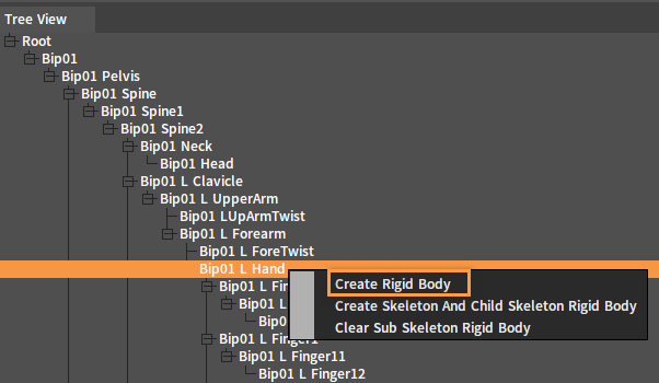
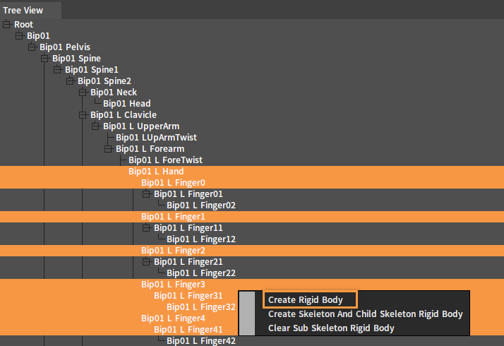
Select a bone and create a Rigid Body for it. In the Tree View panel, select a single bone or multiple bones at one time, right-click to open the Shortcut Menu and select Create Rigid Body.
Single selection:
Multiple selection:
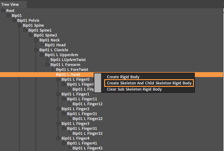
Create Rigid Bodies for all bones in the bone chain. In the Tree View panel, select a bone, right-click it to open the Shortcut Menu, and select Create Skeleton And Child Skeleton Rigid Body to create Rigid Bodies for the selected bone and its child bones.
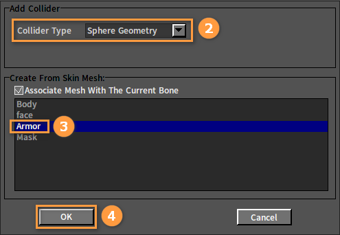
In the pop-up window, make the settings as needed and click the OK button to complete creating the Rigid Bodies.
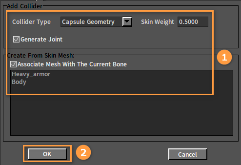
| Property | Description |
|---|---|
| Collider Type | This option defines the type of Collider used by the Rigid Body of the newly created ragdoll. |
| Skin Weight | When creating the Rigid Body for the bone, information on the skin vertices associated with the bone is collected. The skin weight defines the threshold of the blend weight of these vertices with the bone, and vertices with blend weight larger than the threshold will be involved in creating the Rigid Body. |
| Generate Joint | Whether to generate joints automatically. If Generate Joint == true,and a Rigid Body is created for the parent bone of the current bone, then a joint will be automatically created between the two Rigid Bodies. |
| Create From Skin Mesh | Create From Skin Mesh is a list of skins associated with the currently selected bone, from which you select a skin to create the Rigid Body. When an item in the list is selected, the skin corresponding to the animation character in the Scene panel will light up. The Rigid Body is created by selecting the appropriate skin. 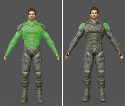 The left part of the above picture is the effect of selecting the mask Heavy_armor, and the right part is the effect of selecting the mask Body. |
Deleting Rigid Bodies
Method 1
Delete a Rigid Body with the Delete shortcut key. In the Tree View panel, select the Rigid Body to be deleted and press the Delete key to delete it.

Method 2
Delete a Rigid Body in the Tree View panel. Select the single Bone Node to be deleted in the Tree View panel and right-click it to open the Shortcut Menu.
| Menu Item | Description |
|---|---|
| Delete Current Bone Rigid Body | Delete the Rigid Body of the currently selected Bone Node. |
| Clear Sub Bone Rigid Body | Clear the Rigid Bodies of all child nodes under the current Bone Node. |
| Delete All | Delete the Rigid Bodies of the current Bone Node and its child nodes. |
In the Tree View panel, multi-select Bone Nodes to be deleted at one time, right-click to open the Shortcut Menu and select Delete Selected Rigid Body/Collider.
Adding Colliders
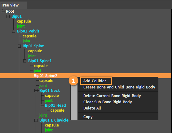
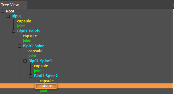
In the Tree View panel, select a bone or a Rigid Body, right-click it to open the Shortcut Menu and select Add Collider, then set the parameters in the pop-up window, and click the OK button to finish adding.
After adding:
Deleting Colliders
Method 1
Delete a joint with the Delete shortcut key. In the Tree View panel or Scene panel, select the Collider to be deleted and press the Delete key to delete it.
Method 2
Delete a Rigid Body in the Tree View panel. In the Tree View panel, select the Collider to be deleted, right-click it to open the Shortcut Menu and select Delete Collider.
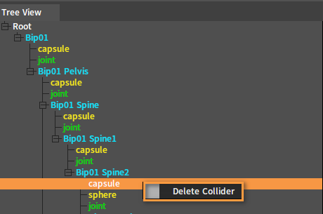
Note: If a Rigid Body has only one Collider, when the Collider is deleted, the Rigid Body will be deleted as well.
Creating Joints
In the Tree View panel, select 2 Rigid Bodies that need creating a joint, right-click to open the Shortcut Menu and select Create Specified Bone Joint.
Deleting Joints
Method 1
Delete a joint with the Delete shortcut key. In the Tree View panel or the Scene panel, select the joint to be deleted and press the Delete key to delete it.
Method 2
Delete a joint in the Tree View panel. In the Tree View panel, select the joint to be deleted, right-click it to open the Shortcut Menu, and select Delete Joint to delete it.
Editing Rigid Body Properties
In the Tree View panel, select the Rigid Body to be edited. Rigid Body related properties can be edited in the Rigidbody Detail panel.
Rigid Body Common Property

| Property | Description |
|---|---|
| Rigid Type | Rigid Body type |
| Name | Rigid Body name. In the ragdoll editing, the name of the Rigid Body is the same as that of its corresponding animation skeleton. |
| Enable Simulate | Specify whether the Rigid Body is involved in the physics simulation. If Enable Simulate == false, the Rigid Body will not participate in the physics simulation. Specifically, there will be no collisions with other objects involved in the simulation, and the model's position will not be controlled by physics. This setting does not affect Rigid Bodies being detected by scene collision queries. |
| Enable Control Constraint | The switch of the Rigid Body's control joint. When Enable Control Constraint == true, a special joint will be created to connect to the Rigid Body. The position of the control joint will always be consistent with the animation position of the skeleton. The usage of this joint is entirely user-defined, e.g. In physics animations, it can be used to constrain the relative motion range between the Rigid Body and the animation skeleton, thus solving the problem that the Rigid Body swings too much in some actions with a large range of motion. Or it can be used to fix the character in a certain position in world space by controlling the joint. |
Other Rigid Body properties (Rigid Body properties, Dynamic Rigid Body properties) are described in detail in the section Editing Properties of Rigidbodies of Rigidbody Editor.
Editing Collider Properties
In the Scene panel and the Tree View panel, select the Collider to be edited. Edit the Collider related properties in the Rigidbody Detail panel.
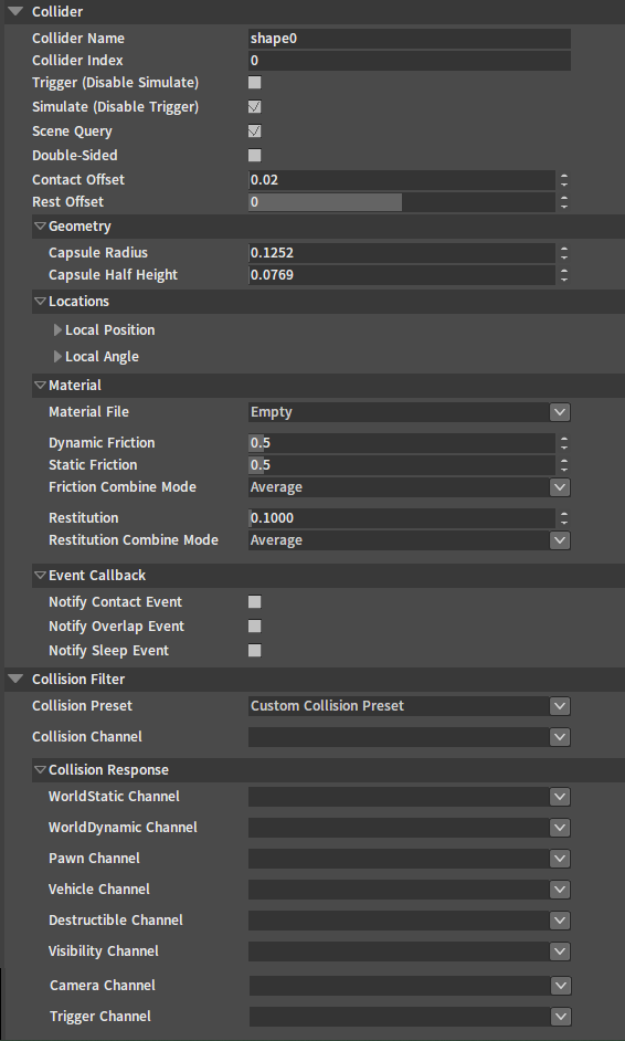
Refer to the section Editing Collider Properties of Rigidbody Editor for Collider properties.
Editing Joint Properties
Select the joint to be edited in the Tree View panel, and edit its related properties in the Rigidbody Detail panel.
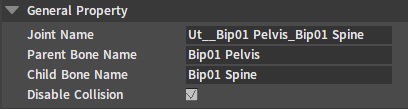
General Properties
| Property | Description |
|---|---|
| Joint Name | Name of the currently selected joint. |
| Parent Bone Name | Name of the currently selected parent bone of the joint. |
| Child Bone Name | Name of the currently selected child bone of the joint. |
| Disable Collision | Disable collisions between parent and child bones. |
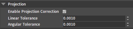
Projection
| Property | Description |
|---|---|
| Enable Projection Correction | Projection Correction will force to pull Rigid Bodies beyond the linear or rotation limit back into the limit. Projection is a very good way to ensure the stability of the joint constraint, though it may lead to simulation results that are not very "physics". |
| Linear Tolerance | When the distance of the Rigid Body beyond the constraint is larger than this tolerance value, the projection will take effect. Note: Setting a tolerance value that is too small will result in jitter. |
| Angular Tolerance | When the angle of the Rigid Body beyond the constraint is larger than this tolerance value, the projection will take effect. Note: Angular Projection is only available when two or three angles are locked. |
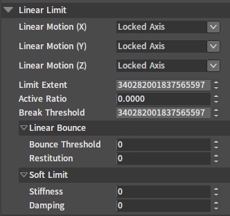
Linear Limit
| Property | Description |
|---|---|
| Linear Motion (X/Y/Z) | Used to limit the linear motion of the joint child bone's Rigid Body relative to the X/Y/Z axis of the parent bone's Rigid Body.
|
| Limit Extent | Specify the maximum motion distance of the child bone's Rigid Body relative to the parent bone's Rigid Body. |
| Active Ratio | The range of the value is [0,1]. The larger the value, the faster the joint constraint is activated, the less likely the constrained Rigid Body is to go beyond the constraint, and the greater the performance consumption. |
| Break Threshold | This value determines how much torque will break the joint. |
| Bounce Threshold | This value defines the minimum impact velocity that causes a bounce. |
| Restitution | This value determines the Rigid Body's bounce speed after it reaches the constraint position. For example, if the value is 0, the Rigid Body will stop when it reaches the constraint position. While if the value is 1, the Rigid Body will bounce at the same speed as when it reaches the constraint position. |
| Stiffness | When the value is larger than 0, the joint's Soft Constraint feature will be turned on. Soft Constraint allows the child bone Rigid Body to move beyond the constraint range. When the Rigid Body's position is beyond the constraint range, the joint will generate a force in the opposite direction to pull the Rigid Body back into the constraint range. The larger the Stiffness value, the stronger the force that pulls the Rigid Body back into the constraint range. |
| Damping | When the value is larger than 0, the joint's Soft Constraint feature will be turned on. Soft Constraint allows the child bone's Rigid Body to move beyond the constraint range. When the Rigid Body's position is beyond the constraint range, the joint will generate a force in the opposite direction to pull the Rigid Body back into the constraint range. The larger the Damping value, the stronger the damping when the Rigid Body is pulled back into the constraint range, and the more slowly the Rigid Body is pulled back into the constraint range. |
Rotation Limit
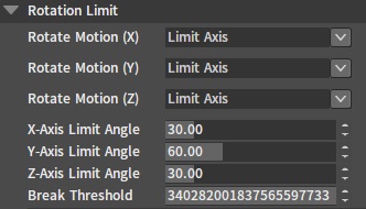
| Property | Description |
|---|---|
| Rotate Motion (X/Y/Z) | Used to limit the rotate motion of the joint child bone's Rigid Body relative to the X/Y/Z axis of the parent bone's Rigid Body.
|
| Limit Angle(X/Y/Z) | Specify the maximum rotation angle of the child bone's Rigid Body relative to the parent bone's Rigid Body. |
| Break Threshold | This value determines how much torque will break the joint. |
Swing Limit
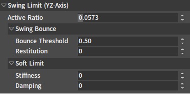
| Property | Description |
|---|---|
| Active Ratio | The range of the value is [0,1]. The larger the value, the faster the joint constraint is activated, the less likely the constrained Rigid Body is to go beyond the constraint, and the larger the performance consumption. |
| Bounce Threshold | This value defines the minimum impact velocity that causes a bounce. |
| Restitution | This value determines the Rigid Body's bounce speed after it reaches the constraint position. For example, if the value is 0, the Rigid Body will stop when it reaches the constraint position. While if the value is 1, the Rigid Body will bounce at the same speed as when it reaches the constraint position. |
| Stiffness | When the value is larger than 0, the joint's Soft Constraint feature will be turned on. Soft Constraint allows the child bone's Rigid Body to rotate beyond the constraint range. When the Rigid Body's rotation is beyond the constraint range, the joint will generate a force in the opposite direction to pull the Rigid Body back into the constraint range. The larger the Stiffness value, the stronger the force that pulls the Rigid Body back into the constraint range. |
| Damping | When the value is larger than 0, the joint's Soft Constraint feature will be turned on. Soft Constraint allows the child bone's Rigid Body to rotate beyond the constraint range. When the Rigid Body's rotation is beyond the constraint range, the joint will generate a force in the opposite direction to pull the Rigid Body back into the constraint range. The larger the Damping value, the stronger the damping when the Rigid Body is pulled back into the constraint range, and the more slowly the Rigid Body is pulled back into the constraint range. |
Twist Limit
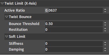
| Property | Description |
|---|---|
| Active Ratio | The range of the value is [0,1]. The larger the value, the faster the joint constraint is activated, the less likely the constrained Rigid Body is to go beyond the constraint, and the larger the performance consumption. |
| Bounce Threshold | This value defines the minimum impact velocity that causes a bounce. |
| Restitution | This value determines the Rigid Body's bounce speed after it reaches the constraint position. For example, if the value is 0, the Rigid Body will stop when it reaches the constraint position. While if the value is 1, the Rigid Body will bounce at the same speed as when it reaches the constraint position. |
| Stiffness | When the value is larger than 0, the joint's Soft Constraint feature will be turned on. Soft Constraint allows the child bone's Rigid Body to rotate beyond the constraint range. When the Rigid Body's rotation is beyond the constraint range, the joint will generate a force in the opposite direction to pull the Rigid Body back into the constraint range. The larger the Stiffness value, the stronger the force that pulls the Rigid Body back into the constraint range. |
| Damping | When the value is larger than 0, the joint's Soft Constraint feature will be turned on. Soft Constraint allows the child bone Rigid Body to rotate beyond the constraint range. When the Rigid Body's rotation is beyond the constraint range, the joint will generate a force in the opposite direction to pull the Rigid Body back into the constraint range. The larger the Damping value, the stronger the damping when the Rigid Body is pulled back into the constraint range, and the more slowly the Rigid Body is pulled back into the constraint range. |
Linear Drive
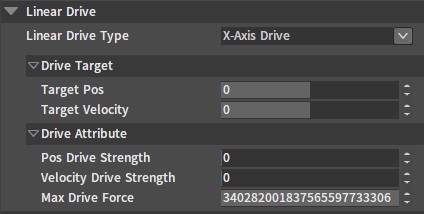
| Property | Description |
|---|---|
| Linear Drive Type | A driving force is generated in the specified axis direction to make the child bone's Rigid Body reach the specified target position or make a uniform motion after reaching the target velocity.
|
| Target Pos | Set the drive target position in the specified axis direction according to Linear Drive Type. |
| Target Velocity | Set the drive target speed in the specified axis direction according to Linear Drive Type. |
| Pos Drive Strength | Set the strength to drive the Rigid Body to the target position in the specified axis direction according to Linear Drive Type. |
| Velocity Drive Strength | Set the strength to drive the Rigid Body to the target velocity in the specified axis direction according to Linear Drive Type. When Target Velocity is set to 0, Velocity Drive Strength can be seen as the linear drive damping. |
| Max Drive Force | Limit the maximum linear drive the joint can generate. |
Rotation Drive
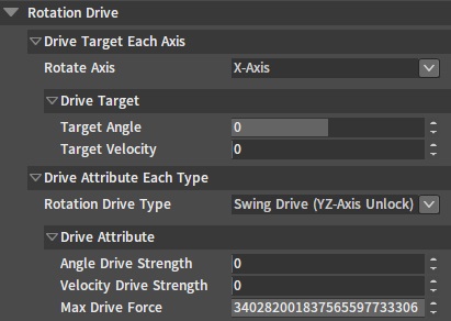
| Property | Description |
|---|---|
| Rotate Axis | Switch the axis that specifies the drive target parameter.
|
| Target Angle | Set the drive target angle in the specified axis direction according to Rotate Axis. |
| Target Velocity | Set the drive target speed in the specified axis direction according to Rotate Axis. |
| Rotate Drive Type | Select the corresponding drive type according to the rotation constraint setting of the joint, so as to achieve the rotation drive effect.
|
| Max Drive Force | Limit the maximum rotation torque the joint can generate. |
Animation Drive
The parameter settings of Animation Drive only take effect when the Physics Animation feature is enabled for the character ragdoll.

| Property | Description |
|---|---|
| Anim Drive Stiffness | The strength of the joint driving the Rigid Body to reach the skeletal animation position when playing the physics animation. |
| Anim Drive Damping | The damping of the joint driving the Rigid Body to reach the skeletal animation position when playing the physics animation. |
| Parent Dominates | When this option is checked, the mass and inertia of all joint parent bones are infinite relative to child bones. Meanwhile, it will be difficult to affect the position of the parent Rigid Body through the joint's child Rigid Body anymore. |
| Parent Mass Scale Coefficient | Scale the mass of the joint parent Rigid Body. A reasonable scaling factor enhances effects of physics animation. |
| Parent Inertia Scale Coefficient | Scale the inertia of the joint parent Rigid Body. A reasonable scaling factor enhances effects of physics animation. |
| Child Mass Scale Coefficient | Scale the mass of the joint child Rigid Body. |
| Child Inertia Scale Coefficient | Scale the inertia of the joint child Rigid Body. |
Editing Save/Save as the Ragdoll

| Feature | Description |
|---|---|
| Save As | Save the currently edited ragdoll as another ragdoll configuration with a user-specified name. |
| Save | Save the current ragdoll edits. |
Simulate

| Feature | Description |
|---|---|
| Simulate | Click the button to start or end the simulation. According to the number of selected Rigid Bodies/joints in the scene at the beginning of the simulation, there are the following simulation methods:
|
Ragdoll Preset
Implementing physics animations for different character actions may require different ragdoll configurations (e.g. character death, climbing, swimming, driving a vehicle, etc.). Ragdoll Preset provides the ragdoll with the ability to create and switch between different ragdoll configurations.
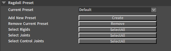
| Property | Description |
|---|---|
| Current Preset | Used to switch between ragdoll preset configurations in the Ragdoll Editor. |
| Add New Preset | Create and add a new ragdoll preset. |
| Remove Cur Preset | Remove the ragdoll preset selected in Current Preset. |
| Select Rigids | Select all Rigid Bodies in Current Preset. |
| Select Joints | Select all joints contained in Current Preset. |
| Select Control Joints | Select all control joints contained in Current Preset. |
Adding New Ragdoll Presets
Click the blank space in the Scene panel, then in the Rigidbody Detail panel, click the Create button of Add New Preset, enter the Preset Name of the ragdoll in the pop-up window, and click the OK button to finish adding. The currently edited ragdoll will automatically switch to the new ragdoll preset.
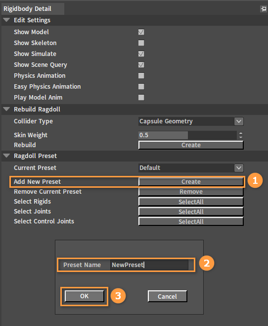
| Property | Description |
|---|---|
| Preset Name | Name of the newly created ragdoll preset. |
After adding a new preset, 2 new function buttons Add To Ragdoll Preset and Remove From Ragdoll Preset will appear in the Toolbar. And the tree nodes in the Tree View panel will turn gray.
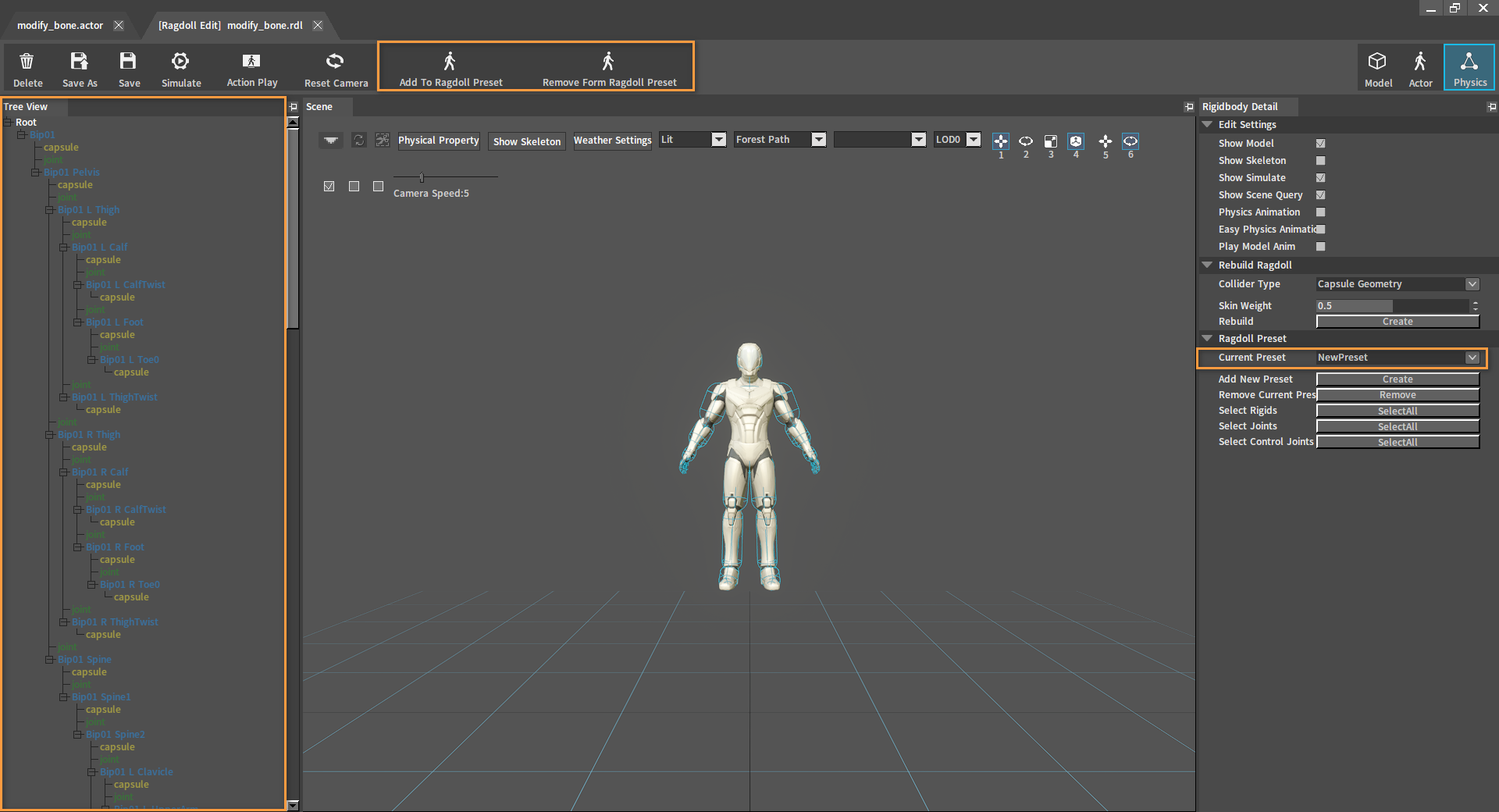
| Button | Description |
|---|---|
| Add To Ragdoll Preset | Add the currently selected Rigid Body/joint to the current ragdoll preset. Default contains all the bones and joints of the ragdoll by default. |
| Remove From Ragdoll Preset | Remove the currently selected Rigid Body/joint from the current ragdoll preset. |
Add Rigid Bodies and joints to the preset. In the Scene panel or Tree View panel, select a Rigid Body/joint and click Add To Ragdoll Profile to add it to the current ragdoll preset.
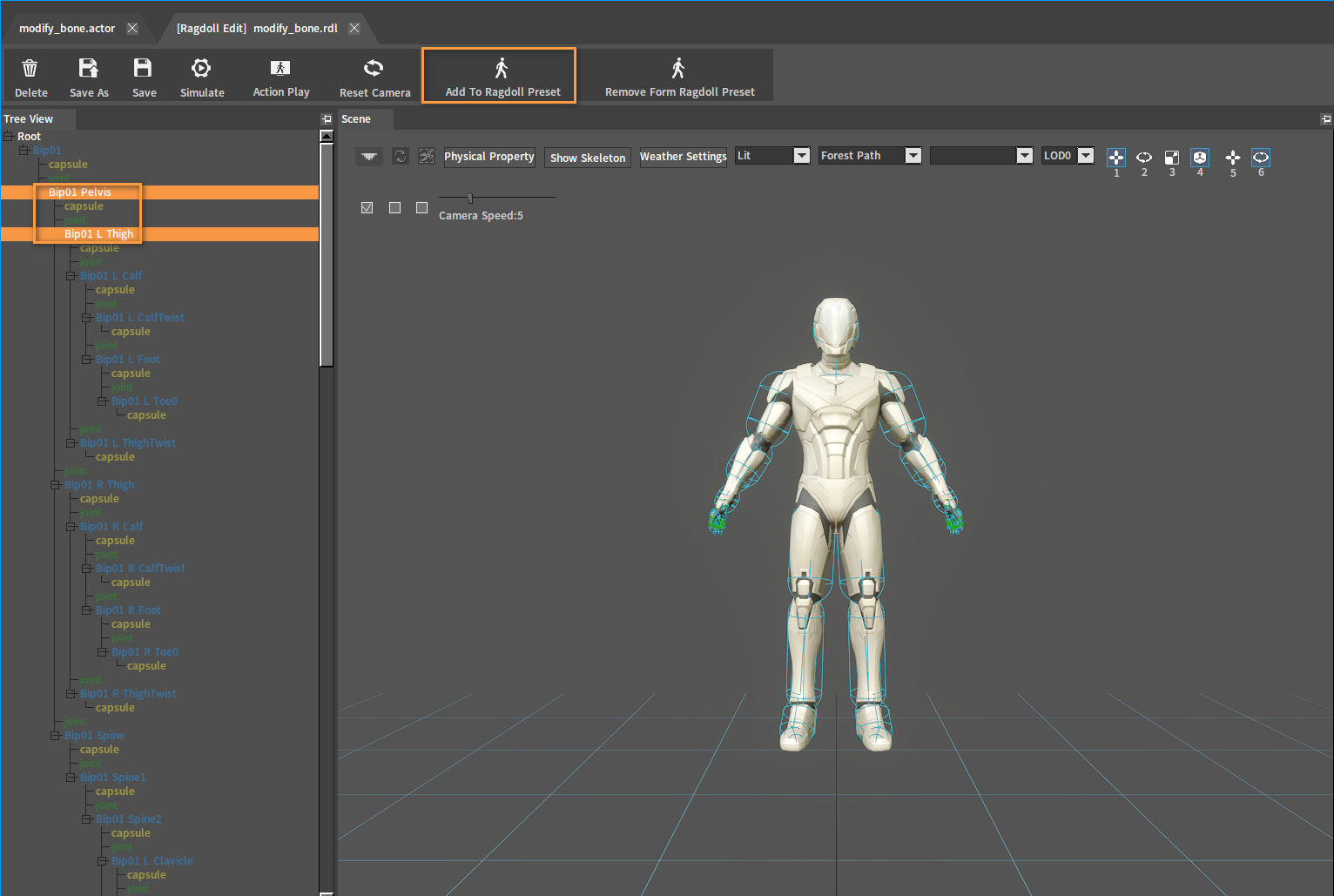
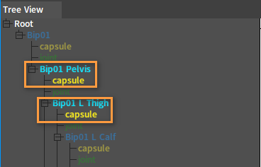
In the Tree View panel, the tree node colors corresponding to the Rigid Bodies/joints added to the ragdoll preset will light up.
Note: Editing properties of Rigid Bodies/joints that are not in the preset in the current preset, is equal to modifying property configurations of Rigid Bodies/joints in Default.
Ragdoll Editing Process
A ragdoll with stable effects can be obtained through the following process.
Creating Ragdolls and Deleting Extra Rigid Bodies
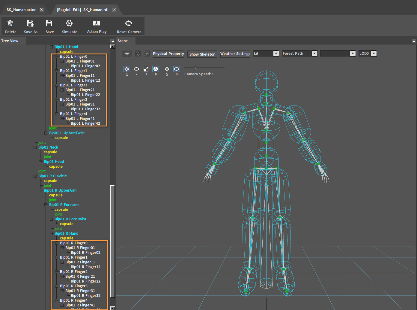
After Creating Ragdolls, a Rigid Body is created for each bone. Check Show Skeleton under Edit Settings in the Rigidbody Detail panel to show the entire skeleton of the character. The entire skeleton can be seen clearly after unchecking Show Model.
Delete unwanted Rigid Bodies(e.g. Rigid Bodies of the character's finger bones) according to the Deleting Rigid Bodies section.
After deleting:
Adjusting the Position of Colliders and Joints
Adjust the position and the size of the Collider until it fits the skin. Select the Collider to be modified in the Tree View panel, then adjust the Collider's size and position in Geometry and Locations of the Rigidbody Detail panel, or by the Switch Axis Editing Mode buttons in the Scene panel. If you think the original geometry of the Collider does not suit the skin, you can delete the original Collider by referring to Deleting Colliders, and then add another Collider containing other shape of geometry by referring to Adding Colliders.
Adjust the joints so that they align with the animation skeleton. Select the joint to be adjusted in the Scene panel or the Tree View panel, and adjust its position by the Switch Axis Editing Mode buttons in the Scene panel.
Adjust the Rigid Body to the appropriate position and size for the skin.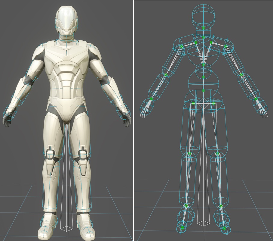
After adjustment, click the Simulate button to perform a simulation. And if the character falls on the ground normally, you can go to the next setting. If the ragdoll behaves incorrectly (such as flying in the air), check whether there are 2 Rigid Bodies interpenetrating each other.
Falling normally:
Flying in the air:
Rigid Bodies interpenetrate each other and the simulation performs incorrectly as shown below:
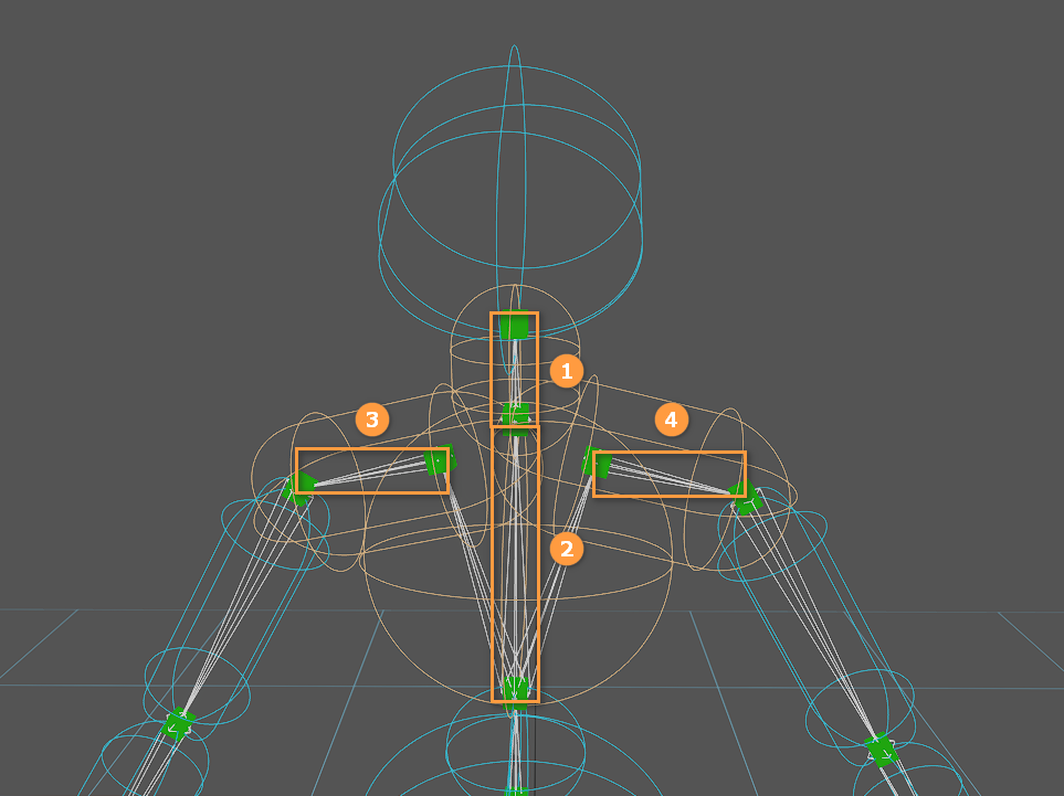
The occurrence of bones that interpenetrate and collide with each other is the main reason why the simulation performs incorrectly.
According to the figure above, the Rigid Bodies of Bone 1 and Bone 2 are interpenetrating each other, but the two bones are connected by a joint which blocks the collision between the two bones by default. However, the Rigid Body of Bone 1 is also interpenetrating the Rigid Bodies of Bone 3 and Bone 4, and there were no joints connecting Bone 1 to them before, so there were collisions among Bone 1, Bone 3 and Bone 4. This leads to the incorrect simulation performance.
Important Rigid Body Properties
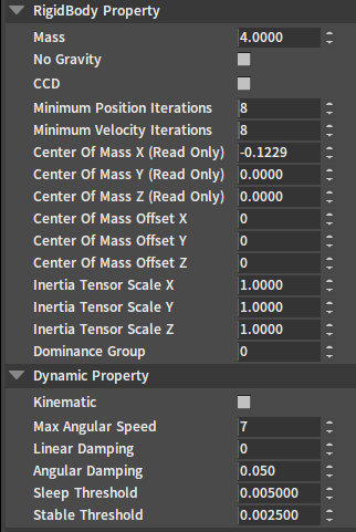
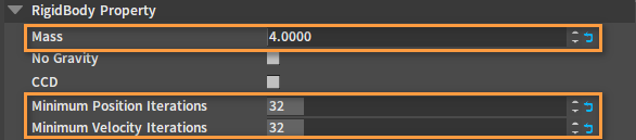
Select the Rigid Body and edit the properties below under the RigidBody Property option of the Rigidbody Detail panel.
| Property | Description |
|---|---|
| Mass | Set the masses of the Rigid Bodies in order, starting from the one at the end of the skeleton tree. The mass of a joint's child Rigid Body must be smaller than that of the parent Rigid Body, so that the joint effects are stable. The mass ratio between the parent and child Rigid Bodies can be set at about 2~10 times |
| Minimum Position Iterations | A value of 32 or so will yield a better result. The appropriate value can be tested by continual simulation debugging. The larger the value, the larger the simulation consumption. |
| Minimum Velocity Iterations | A value of 32 or so will yield a better result. The appropriate value can be tested by continual simulation debugging. The larger the value, the larger the simulation consumption. |
Important Joint Properties
Select the joint and edit the properties below in the Rigidbody Detail panel.
| Property | Description |
|---|---|
| Rotation Limit | Setting the rotation limit correctly for each joint is a must. |
| Projection | Enabling joint projection can greatly improve the stability of the joint. |
Note:
- While editing, you can continually simulate a single joint to see the constraint effect.
- You can edit the joint constraints on one side of the character's body first, and then copy the edits of the joints from one side of the body to the other side by using the copy and paste functions provided by the right-click menu of the Tree View panel.
Adjusting Physics Animation Effects
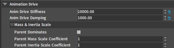
Select a joint and edit the properties below under the Animation Drive option of the Rigidbody Detail panel.
| Property | Description |
|---|---|
| Anim Drive Stiffness | These two properties are the basic property values of the physics animation, and the initial values can be set to 10000 and 1000 respectively. |
| Anim Drive Damping | |
| Parent Dominates | These three properties can all be used to solve the problem of position differences between physics animation and animation data. The difference is that turning on Parent Dominates is equivalent to setting Parent Mass Scale Coefficient and Parent Inertia Scale Coefficient to 0 (0 is equivalent to an infinite value). |
| Parent Mass Scale Coefficient | |
| Parent Inertia Scale Coefficient |