AI Navigation Development Instruction
Overview
The Navigation module is mainly used to provide pathfinding for the AI character. The Navigation Mesh is generated based on the Collision Geometry information in the game world.
Prerequisites
Open the level after creating it in the Component Editor, and check Use Navigation under Navigation of LSceneSettings-1.

Creating Nav Related Features
Navigation Mesh Bounds Volumes
Mark the current coverage and generate NavData (Only available in Tile mode for now, other modes will be added later).
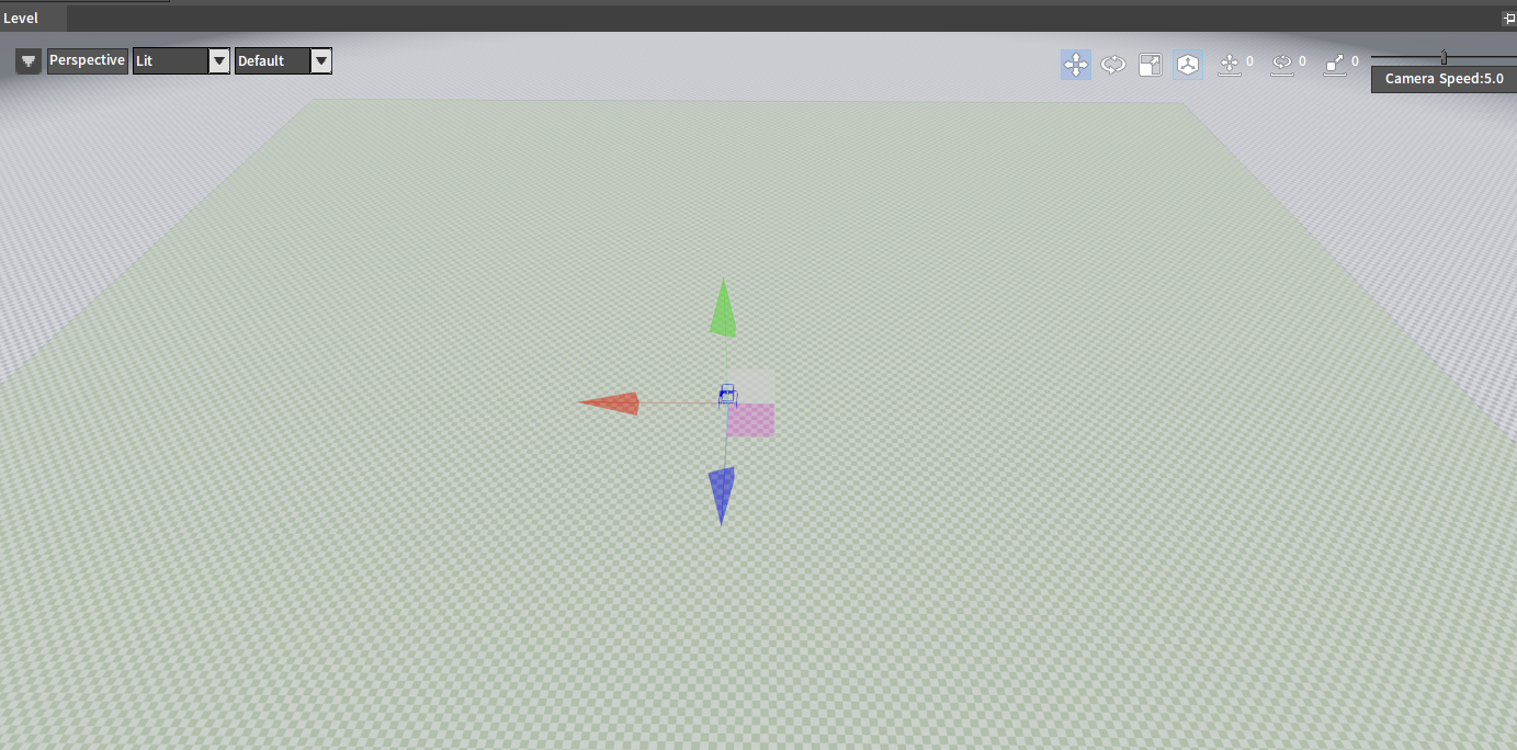
Creating Navigation Mesh Bounds Volumes
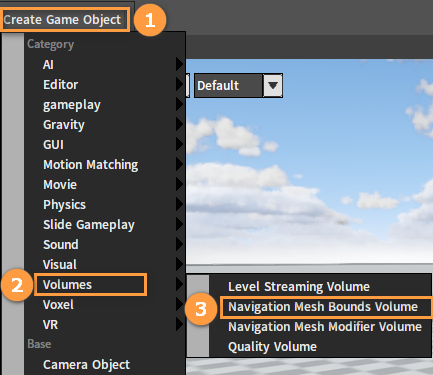
Click Create Game Object -> Volumes -> Navigation Mesh Bounds Volume in the Toolbar.
Deleting Nav Region
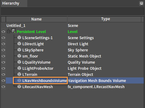
After deleting the LNavMeshBoundsVolume Object in the Hierarchy panel, the corresponding Nav region can be deleted as well.
Adding Nav Region
Method 1: Add a new Navigation Mesh Bounds Volume Object.
Method 2: Move the existing Navigation Mesh Bounds Volume Object to the target region (The original NavMesh will be automatically deleted).
Note:
The newly added or moved Navigation Mesh Bounds Volume will automatically load the existing Navigation Meshes in this region. If there is no Navigation Mesh created in this region, it will be automatically generated.
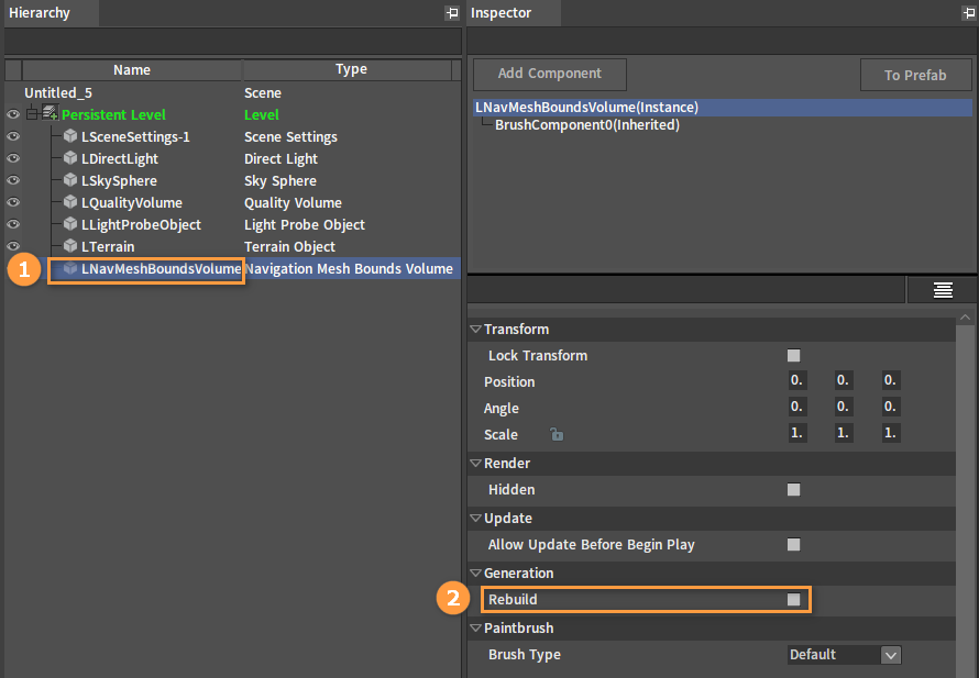
If the Navigation Mesh is not automatically loaded, or it is generated incorrectly, then click the target Navigation Mesh Bounds Volume Object in the Hierarchy panel and click Rebuild under its Generation property to regenerate one.
Adjusting Generation Properties
Select LRecastNavMesh, the Generation Properties are under its Property panel.
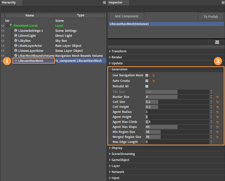
Generation Properties:
| Name | Description |
|---|---|
| Use Navigation Mesh | Whether to use the Navigation Mesh |
| Auto Create | Auto-build NavMesh If unchecked, adding, deleting, updating the NavMeshBounds, and adjusting Generation properties along with other NavMesh-related operations will be affected, while manual rebuild of NavMesh will remain unaffected |
| Rebuild All | Regenerate all Navigation Meshes |
| Tile Size | Region size per generated Navigation Mesh is 256 by default (Measured in Flexi Engine units) |
| Border Size | Border size of each Navigation Mesh region adjacent to |
| Cell Size | Size of each cell after voxelization |
| Cell Height | Height of each cell after voxelization |
| Agent Radius | Radius of the walkable reference target used to generate the Navigation Mesh |
| Agent Height | Height of the walkable reference target used to generate the Navigation Mesh |
| Agent Max Climb | Single step max climb height of the walkable reference target used to generate the Navigation Mesh |
| Agent Max Slope | Singles step max slope of the walkable reference target used to generate the Navigation Mesh |
| Min Region Size | Regions less than this value will be merged |
| Merged Region Size | Regions less than this value will be merged into a larger region |
| Max Edge Length | Max allowed length of contour edges |
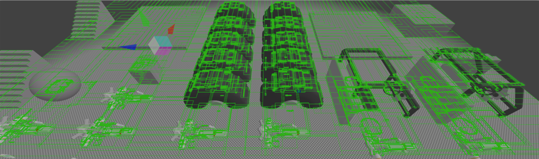
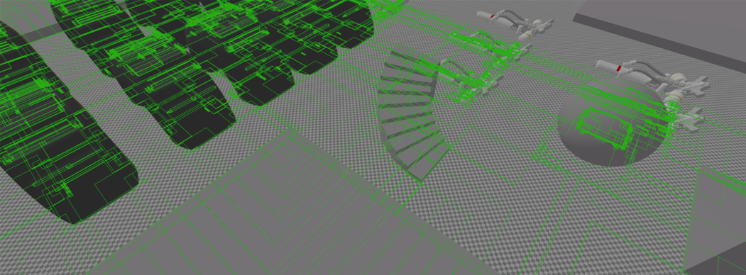
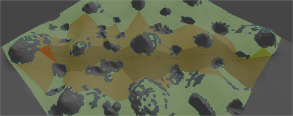
NavData Debug Visualization Modes
Display properties of the LRecastNavMesh Object.
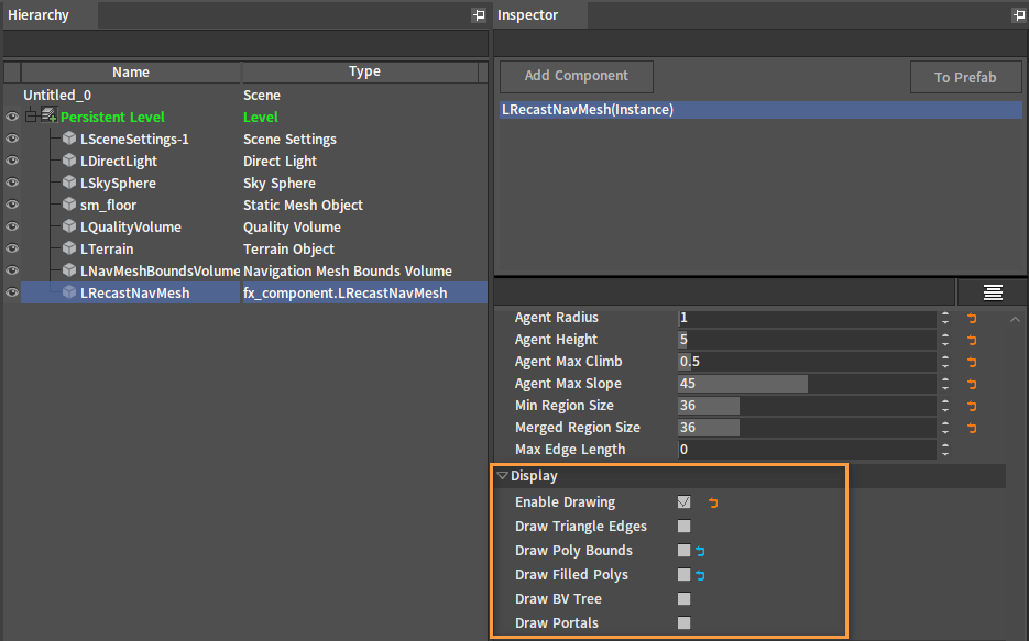
Different Display Modes:
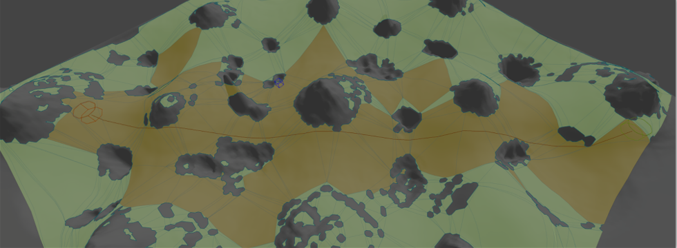
The Visualized Data Mode is mainly used to provide different ways to check if the generated NavData is correct.
Triangle Edges
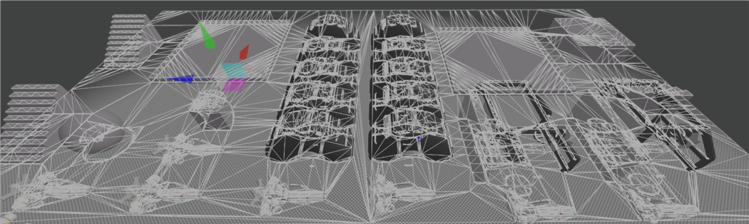
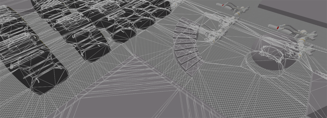
Poly Bounds
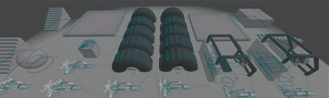
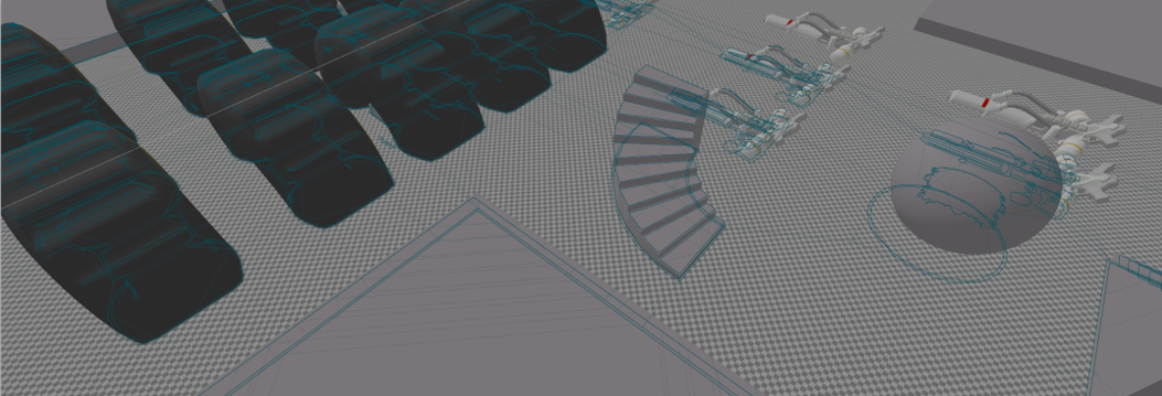
Filled Polys
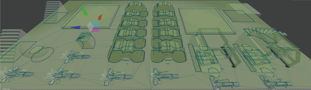
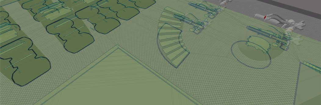
BV Tree
Navigation Tool
The Navigation Tool is used to provide a toolset for validating and testing the NavMesh without coding.
Test NavMesh
It is primarily used to test and observe the Navigation Mesh through the built-in default tools without relying on external code or other features.
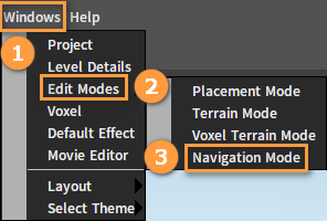
How to Launch:
Click Windows -> Edit Modes -> Navigation Mode.

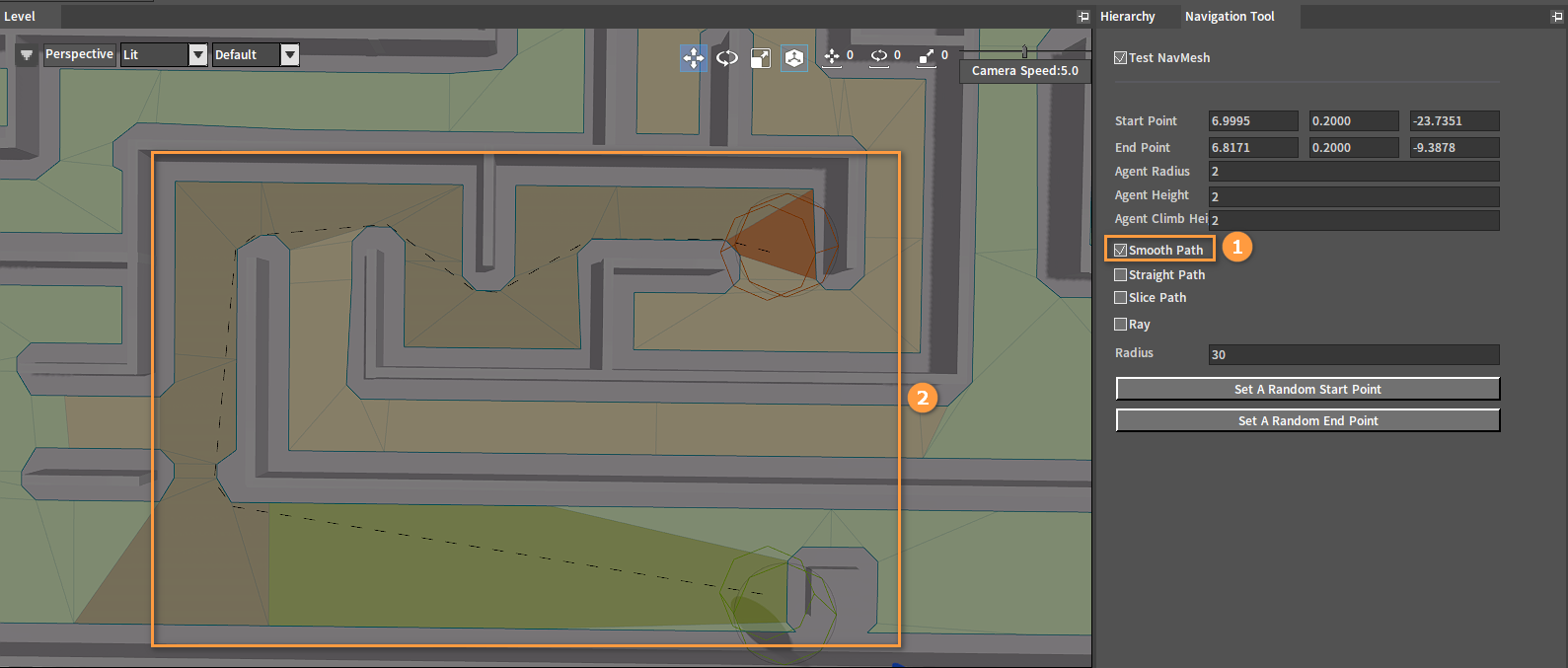
Basic Settings
Check the Test NavMesh in the Navigation Tool panel.
Left-click to set the End Point
Shift + left-click to set the Start Point
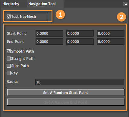
| Name | Description |
|---|---|
| Start Point | Start position of the navigation path (Can be set by left-click on the scene) |
| End Point | End position of the navigation path (Can be set by Shift plus left-click on the scene) |
| Smooth Path | Smooth path |
| Straight Path | Straight path |
| Slice Path | Slice path |
| Ray | Draw rays |
| Radius | Generate the scope of radius randomly |
| Set A Random Start Point | Set a random start position |
| Set A Random End Pont | Set a random end position |
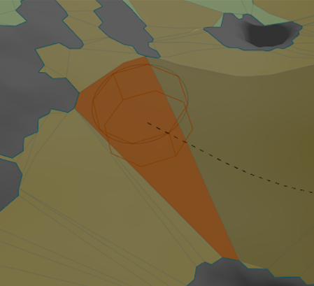
Smooth Path
Draw a Smooth Path between the Start and End Points.
Start Point:
End Point:
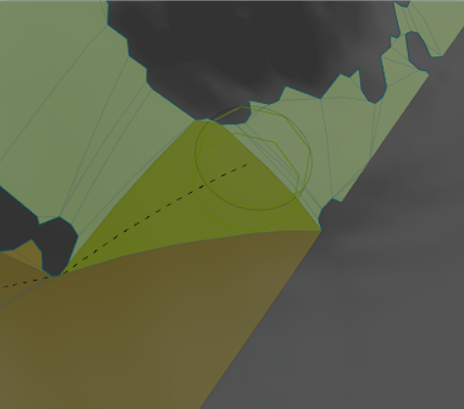
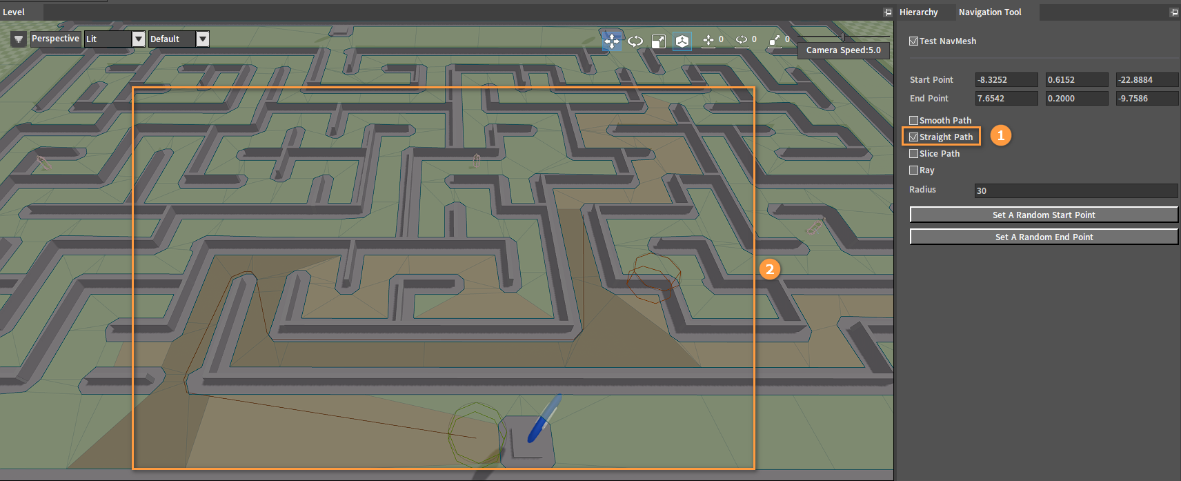
Straight Path
Draw a Straight Path between the Start and End Points.
Slice Path
Draw a Slice Path Animation between the Start and End Points.
Ray
Draw a Ray between the Start and End Points.